JN,
Thank you for the reply. The amplifier will be a modified version of the amplifiers on the Slewmaster thread. Now I understand that you can twist all parallel pairs of pos and neg wire pairs together and that will take care of the majority of problems with connections, is there a minimum twist value or is it the faster the twist the better? Also when you have multiple ground wires going to a star ground with no positive pairing does it also help there to do any twisting of those leads where possible or does the effect only work when it is a pos and neg pair of wires. Any advantage to twisting ground wires together?
Thank you for the reply. The amplifier will be a modified version of the amplifiers on the Slewmaster thread. Now I understand that you can twist all parallel pairs of pos and neg wire pairs together and that will take care of the majority of problems with connections, is there a minimum twist value or is it the faster the twist the better? Also when you have multiple ground wires going to a star ground with no positive pairing does it also help there to do any twisting of those leads where possible or does the effect only work when it is a pos and neg pair of wires. Any advantage to twisting ground wires together?
Yes, my point precisely. Depending on how you view it, an electron is simply a point (i.e. zero size) or the extent of most of its waveform (which could be quite large if it has a well-defined momentum). These water wave analogies are excellent ways of misleading oneself! In solids, electrons don't behave much like classical particles.QSerraTico_Tico said:It has no specific size.
Faster (or tighter) is better, but there is a point of diminishing returns. Too tight, and you exceed the bending limits on the conductors, which should be no tighter than 5 radii (give or take).JN,
Thank you for the reply. The amplifier will be a modified version of the amplifiers on the Slewmaster thread. Now I understand that you can twist all parallel pairs of pos and neg wire pairs together and that will take care of the majority of problems with connections, is there a minimum twist value or is it the faster the twist the better?
When twisting, typically one uses a drill. Great for long lines, but for small stuff, twist while allowing the free ends to float. More difficult, but it doesn't twist the individual wires, so the pair will not try to unravel and open like the drill twisted wires do.
Twist hot/neutral together, ground should be close but not necessarily twisted.
Twist all three dc supply wires together. That way, pos and neg rail feeds are countered by the ground, and cross conduction is also negated.
Also when you have multiple ground wires going to a star ground with no positive pairing does it also help there to do any twisting of those leads where possible or does the effect only work when it is a pos and neg pair of wires.
The intent is to keep current loops as small as practical as well as victim loops. The intent of a ground is to provide a reference for all the circuits. If you run a ground that has current flowing next to one that is low level reference, the current could impact the ground of the low level.
Any advantage to twisting ground wires together?
Only if there is a need to. Proximity forced by twisting is indeed a good thing.
When I examine a specific construct for grounding concerns, I think of it this way: Imagine you're in a room, with an electrical box on the ceiling and an outlet near the door. Take a meter and measure the potential between the two grounds. Depending on the locale, you might find several volts AC. It's not IR drop, but the integrated total of the time varying flux being trapped between the two wires connecting the two points. The only way for your meter to read zero here, is if that loop traps exactly zero total flux. The only absolute way to guarantee that is if the meter wire takes the exact same path between points as the grounding connection. Twisting grounds gets pretty close to that. Using coaxial grounds will also do that.
jn
Last edited:
Thank you JN,
I actually copy and pasted this into a word document so I don't have to look for it later. Great information and help.
Steven
I actually copy and pasted this into a word document so I don't have to look for it later. Great information and help.
Steven
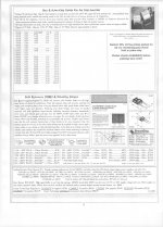
Examples of what we normally use for our power diodes:
The FRED's are good devices, I'd also recommend that kind of diode.
Note that the recovery waveforms are the removed charge style testing, with inductively fed controlled slew rate for turnoff. By design, that setup will force ringing when a diode snaps off, so one must still be wary of verbage. That test, by design, may not be directly applicable to SMPS applications with very fast slews.
I do note that the text of the sheet you provided states the use of 1000 to 1200 volt devices for 350 volt apps, with the statement " to help with turn on surges. Increasing the BVR of the device does NOT increase it's surge capability, it REDUCES it. The only way to increase surge capability is to increase the total silicon surface area, decrease the high current VF by diffusion and base (wafer) resistivity, and increase the heat capacity of the metal bonded to the chip for about the first 100 mils of thickness, to accommodate roughly 8.3 milliseconds of heat capacity.
Other than that, nice pdf John, thanks.
jn
ps..the air core inductor statements are interesting as well. It would be very instructive to actually measure some of those puppies for Ls/Rs as I did for the air core #18and 20 awg in my gallery.
Last edited:
Those inductors would make for some expensive cross-over networks for a bass speaker especially if you were talking 3rd or higher order networks and needed 2 per low pass network per side. Then you would also have the shunt inductors on the high pass side! Is there really going to be a significant sonic difference between these and a normal perfect lay round wire air core inductor?
It can be defined the cross section or wavelength of the electron, but they both are not constant, they depend of the energy and a type of (sub)nuclear processes, which they are obsereved. In the pre-string quantum theory the electron is assumed to be a point (dimensionless) object.
Last edited:
It can be defined the cross section or wavelength of the electron
I don't think much of this is relevant to a simple problem of an audio signal and say a 2m interconnect. At 20kHz the length of the interconnect is a tiny fraction of the signal wavelength and I see no argument to consider anymore than the macroscopic average effect of impurities, etc. (even at 9-9's purity there are still 10^15 or more) on the mobility and hence the simple resistance of the wire.
My experience of the copper foil inductors was pretty disappointing. I got better results from real Litz wire inductors, both lower DCR and higher Q in the audio band.
I will be meeting with these guys http://www.wcmagnetics.com/images/pdf/low-resistance-foil-inductor.pdf later this week to better understand their foil inductors. It looks as though they have some good ideas but they are talking about cored inductors, a different issue. And one that has money riding on it.
I will be meeting with these guys http://www.wcmagnetics.com/images/pdf/low-resistance-foil-inductor.pdf later this week to better understand their foil inductors. It looks as though they have some good ideas but they are talking about cored inductors, a different issue. And one that has money riding on it.
Scott would you say that the interconnect has more to do with quality if insulation, quality of connector attachment and impedance of it over a usable range is the real factor that effect its ability to be a transmission line for low level signals. It may be a salesman look at the tree bark and miss the large cat circling around behind you kind of thing .I don't think much of this is relevant to a simple problem of an audio signal and say a 2m interconnect. At 20kHz the length of the interconnect is a tiny fraction of the signal wavelength and I see no argument to consider anymore than the macroscopic average effect of impurities, etc. (even at 9-9's purity there are still 10^15 or more) on the mobility and hence the simple resistance of the wire.

My experience of the copper foil inductors was pretty disappointing. I got better results from real Litz wire inductors, both lower DCR and higher Q in the audio band.
I will be meeting with these guys http://www.wcmagnetics.com/images/pdf/low-resistance-foil-inductor.pdf later this week to better understand their foil inductors. It looks as though they have some good ideas but they are talking about cored inductors, a different issue. And one that has money riding on it.
Dr Sullivan of Dartmouth...none better.
The only issue I see would be cost vs benefit for the winding method.
jn
the first level of business -
I like to distill things down to the simple-dumb level as much as possible.... so in interconnects -- and assuming a lot of things (like amp stability) --- for the DIY'er;
It is the series inductance that is most important for speaker leads and it is the shunt capacitance that is most important for equipment interconnects.
[thats about as rough and simple as I can imagine]
First level priorities.
For passive inductors, it is the Q that needs to be maintained sufficiently high over the range of freq it is exposed to. Otherwise you wont have the perfect 90 degrees needed/assumed when designing the crossover/filter.
THx-RNMarsh
Last edited:
There is a reason it called Bleeding edge technology.Dr Sullivan of Dartmouth...none better.
The only issue I see would be cost vs benefit for the winding method.
jn
My experience of the copper foil inductors was pretty disappointing. I got better results from real Litz wire inductors, both lower DCR and higher Q in the audio band.
I get the same results with foil inductors.
As you know, I measure everything (thus the constant test equipment purchases).
The best inductors use ceramic/ferrite cores which do not distort under high power and give a high Q. (only ones I have used are sourced from Germany). These will give accurate filter curves.
Air cores do not create distortion but they dont have high enough Q unless they are very large gauge and very large in diameter and made from Litz wire config.
THx-RNMarsh
Last edited:
I would like to comment of my experience with high speed diodes over the years. I worked on my first military project in 1966-7 for Friden-Singer in the SF Bay Area. I did not even know what the final product was, but I did work on the 'unclassified' parts, including running computer simulations of the transient response for switching regulators, one of which we were designing in-house. This is where I saw my first high speed (relatively expensive) power diodes, and our switching frequency was 20KHz or more. There was no direct connection to 50-60Hz regarding these diodes. People must realize that the standard and convenient full wave bridge rectifiers generally used by just about everybody are made with SLOW diodes, not fast ones. You have to pay much more and search far harder for the equivalent high speed full wave bridge rectifier assembly, even today, so why bother when 60 Hz is so low in frequency? This is why even audio designers ignored high speed rectifiers for so long. Why throw money where it is not 'needed'?
When listening tests AND current measurements showed a problem, even at 60 Hz, we had to forgo the convenient and inexpensive full wave bridges and make our own from higher speed, soft recovery rectifier diodes. This became the 'D' mod in the Vendetta Research SCP-2, and it was a hassle to do with the existing power supply boards, but we did it, because our golden eared colleagues could hear the difference. No more and no less. Things became a lot easier when we could make boards for newer products, such as the CTC Blowtorch, the Parasound JC-1,2, and 3, etc. Today, all my best products use essentially the diodes I just posted, or their rough equivalent.
When it comes to twisting wires, I think it is a good thing, so long as they are power supply wires. I learned the technique in 1969 at Ampex Research. It also made the wire bundle more compact and aesthetically pleasing. However, Dr. VDH warned me that tightly twisting AUDIO wires was very bad, as it created more 'micro-cracks' in the wire. So, IF we were to use really good quality audio connecting wire, we should not twist them with a drill. This is why we don't twist the leads in the Vendetta or the Blowtorch. Why bother with quality (expensive) wire, if we are only going to ruin it, by twisting it?
It can be said that a successful audio product is composed of a number of considerations, and high speed diodes as well as no tight twisting of audio hookup wires are two. If you get enough 'right' you tend to win awards for excellence and your product sells for MORE, 20 years later, than for what it did when it is made.
This week, I hope to fix up my Marantz model 10 tuner, which I know from the designer, has a lot of these sort of considerations built in, to make the repair worthwhile.
Last edited:
Demian,
Trying to understand what they are showing in the top two right hand side cutaway drawings. It makes it look like the windings are not complete turns near the gap on those two drawings, long cut and prototype cut. That doesn't make sense, so what is it that I am actually looking at there?
Trying to understand what they are showing in the top two right hand side cutaway drawings. It makes it look like the windings are not complete turns near the gap on those two drawings, long cut and prototype cut. That doesn't make sense, so what is it that I am actually looking at there?
Now, what about CAP differences? This is another area often discussed here, but still appears not well understood.
First, some caps have very high distortion, including virtually all ceramics except NPO (COG) caps that are usually low values only. Even these ceramics have DA or dielectric absorption of relatively high amounts. Electrolytic caps, both tantalum and aluminum types have a lot of DA too, so we avoid them, if possible, except for power supplies.
This is where film caps shine, especially polypropylene, polystyrene, and Teflon. Mylar and PPS, etc, do have a significant amount of DA, even though they have little non-linear distortion, unfortunately, and are not the best choice for hi end audio design.
A final, potentially fatal factor is how the cap is constructed. Is it well damped? If you hit it with your fingernail, does it 'ring'? Many commercial caps have problems both obvious and less so. After all, 'ringing' is not on the spec sheet, so other considerations take over.
Serious designers do not take cap selection lightly. AND usually, LESS IS BEST, when it comes to coupling caps as well.
Last edited:
Demian,
Trying to understand what they are showing in the top two right hand side cutaway drawings. It makes it look like the windings are not complete turns near the gap on those two drawings, long cut and prototype cut. That doesn't make sense, so what is it that I am actually looking at there?
What they are doing is trying to keep the conductor away from the gap, as too close and the dissipation within the wire will go up.
If you could see the magfield intensity lines, it would be intuitively obvious.
I believe Dr. Sullivan has several papers on his Dartmouth website which discusses this. One as I recall, showed how the winding scheme changed vs frequency.
jn
- Status
- Not open for further replies.
- Home
- Member Areas
- The Lounge
- John Curl's Blowtorch preamplifier part II