Is there a SMPS that one can buy off-the-shelf in a variety of power levels that can be recommended? Mfr?
I would like to do a 1 to 1 substitution in an amp and measure/listen.
And compare the HF noise generated to the noise produced by diode rectifiers.
-RM
I would like to do a 1 to 1 substitution in an amp and measure/listen.
And compare the HF noise generated to the noise produced by diode rectifiers.
-RM
Last edited:
Hi, Richard 🙂Is there a SMPS that one can buy off-the-shelf in a variety of power levels that can be recommended? Mfr?
L.C. prefered was Hypex.
The other ones he tested were Connex and Audio power (both regulated, both on this forum).
He had a problem with the AP (smoked), so the test ended before completed.
If you make some extensive measurements, will-you publish them ? i'm very interested in this subject.
It should be interesting to compare PSU and SMPS with, for both, cap multipliers between them and the amps.
Last edited:
Is there a SMPS that one can buy off-the-shelf in a variety of power levels that can be recommended? Mfr?
I would like to do a 1 to 1 substitution in an amp and measure/listen.
And compare the HF noise generated to the noise produced by diode rectifiers.
-RM
These folks have a range of relatively cheap models some have extra filtering and some include rail boost outputs for pre-driver stage.
Connexelectronic
In this case I am just talking about the resistance and what comprises it, from these effects some excess noise at extremely low levels, maybe, THD at any level, don't see it. By extremely low levels I mean the net contribution, excess noise itself goes down very rapidly with excitation so at very low currents there would in fact be even less of an effect, the opposite of what was proposed.
Scott,
I see where we still are not communicating. The FFT's of the output of my analyzer showed a difference in noise level, but that is more likely the way the circuit responds to what is changing.
So either a few other folks can build similar analyzers or we can try wire that deliberately has added defects. Since the issue of twisted pair cable came up (J.N. you have to use a variable speed drill to get nice twisting. Back when the idea first started the common drill was a single speed AC line powered model and the results could be amusing.)
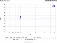
So here are the results of taking ten feet of 24 gauge magnet wire and loosely twisting them versus the same thing twisted as tight as possible, the drill reversed and untwisted and retwisted for a total of five times in each direction.
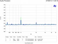
The high level signal is 10 volts at 19,000 and 20,000 hertz. The low level is 10 mV and has the loosely twisted compared to the tightly twisted. The 0 db reference level is 1 volt. Note both high level and low level test show a 20 db range. The low level is 60 db below the high level.
NO SPECIAL GEAR WAS USED. This is a simple test many can repeat.
Attachments
Last edited:
I see where we still are not communicating.
NO SPECIAL GEAR WAS USED. This is a simple test many can repeat.
I don't see that at all, is it communicating if I agree your water analogy makes perfect sense?
Thanks for this though, but there is not enough information to repeat the test. How is the wire connected, with a resistor and generator? What voltage is being sensed. Are two wires twisted together, are they untwisted for the test? So many questions. You need to be precise, so that missed details can maybe be brought to light. Like for instance have you changed the bulk resistance of the wire and what would that effect be? Where is the 1kHz in the first plot coming from? Did you try before/after or start with two samples? You have no control of the starting state so how do you know you added "defects" or if this operation adds any significant defects at all (VdH said so). One last one the blue plots are not 60dB apart at 1kHz but the excitation is just -60db first to second.
Last edited:
Those inductors would make for some expensive cross-over networks for a bass speaker especially if you were talking 3rd or higher order networks and needed 2 per low pass network per side. Then you would also have the shunt inductors on the high pass side! Is there really going to be a significant sonic difference between these and a normal perfect lay round wire air core inductor?
You can check out the explanation here - see the graph and text below
Mundorf foil coils homepage
I don't see that at all, is it communicating if I agree your water analogy makes perfect sense?
Thanks for this though, but there is not enough information to repeat the test. How is the wire connected, with a resistor and generator? What voltage is being sensed. Are two wires twisted together, are they untwisted for the test? So many questions. You need to be precise, so that missed details can maybe be brought to light. Like for instance have you changed the bulk resistance of the wire and what would that effect be? Where is the 1kHz in the first plot coming from? Did you try before/after or start with two samples?
The twisted pair of 24 gauge wire is connected as a balanced jumper from the AP output to the input. It is 50 ohms out and moderate impedance in.
The 1000 Hz on the loosely twisted pair is the same as with a normal mic cable jumper and is probably the residual of the AP.
Yes the resistance will have changed. Do you think a change of a few milliohms would have that effect? It is interesting to note the distortion is lower at a high level signal.
I did two before and after sets, and two just afters, as the befores were all the same. The more you torture the wire the greater the 1000 Hz spike. It is also easier to remove the insulation after the mega twist.
The issue is does something funny happen at low currents due to defects in the wire. So if you try it just be sure to really mangle the wire and use a high impedance A/D input. The source resistance should keep the noise level down.
Please let me know if you have any other questions. I think you will have fun with this.
Now when MMICs first came out one of the things they found was below a certain feature size the noise level dropped. However I can't even remember who it was that made the first MMICs or any papers on it.
A bit confusing is the color scheme what is blue is the first run the second is green. So what is blue on the high level plot is green on the low level one.
Last edited:
The twisted pair of 24 gauge wire is connected as a balanced jumper from the AP output to the input. It is 50 ohms out and moderate impedance in.
So the current in the wire doesn't matter? Moderate, how about infinite? There is no control here as to what is being measured or on the current in the DUT. You say the change in wire resistance doesn't matter but there is not enough information to verify that.
I'm still not clear as to the state of the wire as tested, is the wire tightly twisted or loosely twisted while being measured or are they untwisted and put in the fixture in the same mechanical state. Open magnet wire interconnects are problematic enough at -150+dB.
Last edited:
So the current in the wire doesn't matter? Moderate, how about infinite? There is no control here as to what is being measured or on the current in the DUT.
I'm still not clear as to the state of the wire as tested, is the wire tightly twisted or loosely twisted while being measured or are they untwisted and put in the fixture in the same mechanical state. Open magnet wire interconnects are problematic enough at -150+dB.
The idea is to get the current into the wire as low as possible. At higher current I think the defects are less important. If you like you can terminate the cable with a resistor and I would expect the distortion to drop. My theory says that you can go to great lengths on reducing cable defects or raise the voltage and current so they don't matter.
I first loosely twisted the wire then while twisted connected it to the measurement system. As it is a long loop I fold it in half and roll it up on my hand and then twist it to stay in place. After two test runs I then torture it and retest it the same as before. The twisted pair makes for a nice balanced test cable to reject much noise. The results shown are 1024 averages of the FFT.
Yes the signal is barely above the noise, but it is repeatable in my setup and at a much higher level than a decent cable should provide.
My special system works on unbalanced single conductors and noise is a really big issue.
The idea is to get the current into the wire as low as possible.
So at no current in the wire the distortion is infinite or rises to some limit? Lowering the frequencies and using an electrometer one should get down to pico-amps. There is always some displacement current in the capacitance, which BTW brings up the different L and C of the two cases. Maybe jn could comment, I don't use an AP much.
So at no current in the wire the distortion is infinite or rises to some limit? Lowering the frequencies and using an electrometer one should get down to pico-amps. There is always some displacement current in the capacitance, which BTW brings up the different L and C of the two cases. Maybe jn could comment, I don't use an AP much.
As charge must be conserved there must be a limit. My OPINION is that at very low current levels the distortion and noise will be the limit as the current rises the S/N increases as the distortion decreases.
If you note at high level the distortion is just under 120 db down from the excitation signal. It is just under 110 db at the lower excitation level.
It is possible it is due to a change in the L or C. However I don't think the C will change very much.
I proposed my theory, here are some test results I thank others can duplicate, please feel free to punch holes in the theory based on experiments.
I proposed my theory, here are some test results I thank others can duplicate, please feel free to punch holes in the theory based on experiments.
Just trying to figure out what the theory is, if there is no current in the wire what makes the distortion, there is no current in the postulated defects.
Just trying to figure out what the theory is, if there is no current in the wire what makes the distortion, there is no current in the postulated defects.
The theory says defects in a conductor provide a non uniform media. At low currents this has more of an effect on propagation than at higher currents.
The theory says defects in a conductor provide a non uniform media. At low currents this has more of an effect on propagation than at higher currents.
You do not have a theory, you have a hypothesis.
L and C will be inverse. With contact along the length, LC = 1034 DC, DC being the effective dielectric coefficient of the two wire system with essentially an air dielectric with a smidgen of enamel.
If you change L, you will absolutely change C.
Your experiment is awful in regard to control.
I need to know:
1. What is the twist pitch of the two types.
2. What is the L per foot of the two before and after.
3. What is the C per foot for the two before and after.
4. What is the R per foot for the two, before and after.
5. How does the AP react to the test length given the characteristic impedance of the cable in comparison to the out and in Z of the machine. To wit: is the test setup invariant to the cable's L, R, and C, or is the measurement confounded by these parametrics.
So far, your test variance isn't floating my boat, there is no control over the experiment evident to cover the results.
jn
Light twisting Parallel mode 5.8 mH 1.6Q .0016 nF .025DF. Series Mode 4.5 mH Q1.6 .0016 nF .04DF
After much torture Parallel mode 6.1 mH Q1.5 .00151nF .034 DF Series Mode 4.4mH Q1.5 .00151nF .05 DF
Can't measure resistance change.
Pitch 4 turns per inch.
After much torture Parallel mode 6.1 mH Q1.5 .00151nF .034 DF Series Mode 4.4mH Q1.5 .00151nF .05 DF
Can't measure resistance change.
Pitch 4 turns per inch.
Last edited:
Light twisting Parallel mode 5.8 mH 1.6Q .0016 nF .025DF. Series Mode 4.5 mH Q1.6 .0016 nF .04DF
After much torture Parallel mode 6.1 mH Q1.5 .00151nF .034 DF Series Mode 4.4mH Q1.5 .00151nF .05 DF
Can't measure resistance change.
Pitch 4 turns per inch.
Your inductances are off by three orders of magnitude.
jn
Mili x micro mistake.
I tested this site for uH vs mH.
Ed tested a cable previously using parallel mode, and had the exact same three order of magnitude error. The correct test needs to be Ls/Rs.
In addition, he needs to zero cal the meter, as he will be reading about 150 nH per foot.
1.5 pf is also inaccurate. Capacitance will range from about 14 pf per foot if EDC is 2, to about 28 pf per foot if the EDC is 4.
In my opinion, measurement of inductance and capacitance at this level (nH and pF) is quite a bit easier than what Ed is trying to do with the AP.
jn
Your inductances are off by three orders of magnitude.
jn
Yeah I'll rerun it Thursday with a different bridge. But if the capacitance reading is staying the same so should the inductance.
- Status
- Not open for further replies.
- Home
- Member Areas
- The Lounge
- John Curl's Blowtorch preamplifier part II