This is not to say that nonsense isn't nonsense, but a cap multiplier only filters what comes from upstream. Downstream disturbances such as load variations will get flattened by a Jung reg or comparable circuitry, but . . . .
Maybe misunderstood - I am not advocating ditching a regulator - you need that for load and line regulation.
That is very nice. I suppose one's writing style can't please everyone, and I wish KCP could turn down the cuteness knob several dB, but he does work hard to get to the bottom of things. I'm glad he's found employment doing what he clearly enjoys.As a convenience, here are the 6 parts in one document, from an appropriate site, 😉 ... www.ap.com/download/file/678
I had someone tell me the other day that, from his perspective, the tragic and unexpected loss of Jim Williams has been devastating for Linear Technology --- that there is essentially no one there anymore to help him with applications. This guy is pretty sharp, and resembles some others I know who have dug out electronics, having been formally trained in mechanical engineering. They do well, and often know control systems better than electrical engineers, but the inevitable gaps can be crippling.
Yes, I looked at shunt regs and they work very well. I ended up going the class A route with heavy decoupling - I will have to see how it sounds.
This is not to say that nonsense isn't nonsense, but a cap multiplier only filters what comes from upstream. Downstream disturbances such as load variations will get flattened by a Jung reg or comparable circuitry, but not by a cap multiplier, which doesn't regulate. This in defense of regulators.
Seperate issue, someone above posted that a Jung super reg would also work to filter RF from the supply lines. However, at RF the output impedance of regulators (including the leads to where the juice is needed) gets fairly high and I would recommend local caps for that.
Agree Paul. If you look at the PSRR, Zout, etc of a Jung type reg you always see that the curves bend upwards at higher freq. That is a clear giveaway that the performance suffers above audio. ALL these reg types have that, including the 317 and other integrated types (only worse).
So relying on a Jung reg for RF is nonsense.
Local bypassing with very short loops is the only thing that works at RF.
jan
Impressive stuff ...! 😉Even with fast shunt regs you will not get sufficiently rapid response in some situations. Then you may be advised to sample the signal ahead and with a "plant model" enact precisely-timed compensatory corrections. With deterministic fast pulse generation, compensating loads can be driven to render the power supply drain constant, or with even more parts a balanced system can be used, even if the ultimate outputs are single-ended. I did many of these things in a spectrometer back in the late '70s, a project that took four years of probably 12-15 hour days and usually 7 day work-weeks before the main power switch for the whole system was flipped on.
Prior Preparation Prevents P*** Poor Solder Joints....

Back in my Telecom Repair Lab apprenticeship days, the NASA high reliability soldering course I undertook specified cleaning pcb pads and component leads with an ink eraser, and then further cleaning the pcb pads, component leads AND solder wire with solvent (isopropyl, freon etc) and a particular slightly abrasive tissue paper (I have no idea of the make/model, nowadays I use the harshest toilet tissue...cheap and easily available !).
When the soldering is completed, I use one of these
 containing isopropyl and one of these (larger/largest size),
 and tissue to cleanse/remove all flux remnants.
I keep my solder reel in a ziplock bag, with the solder wire exiting through a hole in the bag, and I (habitually) clean it just prior to use.
High quality solder and close control of soldering iron temperature is another factor in the equation to achieving high quality, long term reliable solder joints.
Funnily enough I have had a repair that I performed 20+ years ago and across the country turn up on my bench, and my solder joints looked as good as new !.
Dan.
....CLEAN YOUR LEADS JUST BEFORE SOLDERING.
Back in my Telecom Repair Lab apprenticeship days, the NASA high reliability soldering course I undertook specified cleaning pcb pads and component leads with an ink eraser, and then further cleaning the pcb pads, component leads AND solder wire with solvent (isopropyl, freon etc) and a particular slightly abrasive tissue paper (I have no idea of the make/model, nowadays I use the harshest toilet tissue...cheap and easily available !).
When the soldering is completed, I use one of these
containing isopropyl and one of these (larger/largest size), and tissue to cleanse/remove all flux remnants.I keep my solder reel in a ziplock bag, with the solder wire exiting through a hole in the bag, and I (habitually) clean it just prior to use.
High quality solder and close control of soldering iron temperature is another factor in the equation to achieving high quality, long term reliable solder joints.
Funnily enough I have had a repair that I performed 20+ years ago and across the country turn up on my bench, and my solder joints looked as good as new !.
Dan.
View attachment 370182
Back in my Telecom Repair Lab apprenticeship days, the NASA high reliability soldering course I undertook specified cleaning pcb pads and component leads with an ink eraser, and then further cleaning the pcb pads, component leads AND solder wire with solvent (isopropyl, freon etc) and a particular slightly abrasive tissue paper (I have no idea of the make/model, nowadays I use the harshest toilet tissue...cheap and easily available !).
When the soldering is completed, I use one of these
View attachment 370184 containing isopropyl and one of these (larger/largest size),
View attachment 370183 and tissue to cleanse/remove all flux remnants.
I keep my solder reel in a ziplock bag, with the solder wire exiting through a hole in the bag, and I (habitually) clean it just prior to use.
High quality solder and close control of soldering iron temperature is another factor in the equation to achieving high quality, long term reliable solder joints.
Funnily enough I have had a repair that I performed 20+ years ago and across the country turn up on my bench, and my solder joints looked as good as new !.
Dan.
Ah.. I now remember what the standard equipped "service tools bag" contained back when I worked at DEC (Digital Equipment Corporation) 😀
That took you a week??? You gotta be kidding me. Shoulda been 10 minutes....tops.For example, it took me a week to work in the subject of cleaning component leads, and then I still got back-wash about how it isn't very important, or flux does it all, etc.
Cleaning the surfaces prior to soldering is very important. Flux cannot clear everything in the timeframe where the flux is active, nor is it supposed to.
Scraping the lead as you are so fond of, works ONLY if you clear surface garbage without removing the tin/lead or tin/silver cover alloy to expose the two copper tin intermetallics. If you do this, the flux may not be able to activate the passivated surface.
If you scrape to copper, then all is well.
The techs looked at you funny because your "process" has a very high probability of screwing up the resultant work the solderers are trying to do.
Tin lead flux has to become active below the 183 C temperature, and typically works for the next 50 degrees or so for a while.
Tin/silver flux has to work just below 221 C and 50 degrees or so above.
Use tin/silver flux for lead/tin, and it may not activate prior to the melting of the solder.
Use tin/lead flux for tin/silver, and it may burn before the solder melts. Use too high a tip temp, you may burn the flux before the flow can be established.
If you go into home depot and buy "lead free" flux, it is named that because it is designed for the lead free temperatures, not because there is no lead within. But watch out, it will contain zinc chloride, not recommended for electronic work due to the residue being so corrosive. If a surface is so bad that it needs plumbing flux to recover the solderability, do NOT use it for stranded wires, and clean the living daylights out of any lead recovered using it. Baking soda can be your friend...
Soldering is a TWO THOUSAND year old technology, yet still you get some egghead coming into the production line with hairbrained ideas and little if any chemistry, metallurgical, or practical experience, mucking up the works.
If it is of any consolation JC, the physicists and engineers in Gevena did the exact same thing on the LHC...so you are in good company. But they only caused 55 thousand pound objects to play leapfrog in the tunnel for a length of a kilometer. Here, we speak about far more technical challenges.... hi end audio..
View attachment 370182
Back in my Telecom Repair Lab apprenticeship days, the NASA high reliability soldering course I undertook specified cleaning pcb pads and component leads with an ink eraser, and then further cleaning the pcb pads,
We used some kind of fiberglass brush. But man, the bristles aggravated the daylights outta the skin...
Be wary of rubber erasers, they may contail sulphur. Further cleaning as you mention is the way to go.
jn
Last edited:
Do It Right The First Time...
Solvent preparatory cleaning is the key to perfect joints...and then solvent clean the flux away....like I said, 20 years later and still perfect joints, and that without conformal coatings.
Dan.
Yup, those FG pens work great but the fine glass particles/fibres just somehow find a way off the bench and straight to the crotch...nasty...brass brush versions are infinitely less hazardous.We used some kind of fiberglass brush. But man, the bristles aggravated the daylights outta the skin...
Be wary of rubber erasers, they may contain sulphur. Further cleaning as you mention is the way to go. jn
Solvent preparatory cleaning is the key to perfect joints...and then solvent clean the flux away....like I said, 20 years later and still perfect joints, and that without conformal coatings.
Dan.
Yup, those FG pens work great but the fine glass particles/fibres just somehow find a way off the bench and straight to the crotch...nasty...brass brush versions are infinitely less hazardous.
Solvent preparatory cleaning is the key to perfect joints...and then solvent clean the flux away....like I said, 20 years later and still perfect joints, and that without conformal coatings.
Dan.
Sheesh...normally I wear clothes when working with fiberglass..😱
But hey, to each his own...😉
Man, I wish we could still use Freon. Nothing came close..
jn
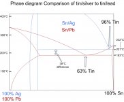
Here's an overlay between lead tin and tin/silver I used for clock repair class.
Red is the lead/tin. Blue is tin/silver.
jn
Funny Jerry Sussman of MIT (physicist and audio tinkerer) is the chairman of a local antique watch/clock collecting/repairing club.
flux contamination
Flux residue tee hee.
Some years back, circa 1995, when I was in the doghouse for taking a hit for some shoddy capacitors sometimes blowing off their cans at about 2V above rated voltage (yes a stupid thing to do, but it would never have been a problem if the anticipated Rubycons were used --- they were temporarily unavailable, and a purchasing agent got some from a bottom-of-barrel outfit that were suitable for a children's toy, the type that get broken a few days after Christmas), the design clean-sheet-of-paper passed over to another consultant, and a very good one.
He rediscovered an approach to power amps in which a single supply gets its ground reference produced by a combination of a moderate-resistance resistive divider and d.c.-coupling the speaker loads to the center tap of two bulk caps in series. The alternative common to these very low-cost powered speakers was a single big bulk cap, and a half-supply referenced to its negative terminal, and finally 'lytics a.c.-coupling the speaker loads. It (the single bulk cap etc.) works, and has certain advantages although probably no real cost savings.
But a technician came to me to complain that something was behaving strangely on the bench. Huge d.c. offsets were moving the speaker cones visibly, and in opposite directions. I tried to figure out what might be happening, and worried that it was something intrinsic to the clever "new" design. I talked to the designer and at one point he said Do you suppose there may be flux contamination?
I got the tech to clean the board and thoroughly dry it out. The problem disappeared. I discovered that the whole lab had gotten (really, lifted) their solder from the Harman speaker lab, and it was some superactive flux, highly ionic and hygroscopic, much loved by the speaker guys as it cut through the accumulation of gorf on the leads of crossover network components in bins, some of which had probably been there since the heyday of James Bullough Lansing himself.
I tried to get them to stop using it to no avail, but I did go round and confiscate all of it in the Multimedia lab and substituted rolls of rosin core.
Funny Jerry Sussman of MIT (physicist and audio tinkerer) is the chairman of a local antique watch/clock collecting/repairing club.
Small world...sheesh.
I used it to discuss a repair where I had to solder in two small plates of brass using tin/silver for making new teeth on a barrel, and then using lead/tin to solder the newly machined barrel onto the gear.
With care, the work can be kept below 215C or so while the lead/tin is being flowed. Normal step soldering process.
jn
Now, some useful input is being put forth.
Many serious builders have tried the fiberglass pencils, and yes they do hurt, if they get into your skin.
I still find that mechanical 'scraping' is the most effective. It takes the entire contaminated external surface off, it isn't too difficult to find the most effective tool in your collection to do it. Usually a narrow type of pliers (I don't have a specific name, offhand) that has a relatively smooth working surface, not serrated, is the best.
Then you don't leave an active residual flux.
Of course, the solder has a useful flux. I chose a medium active type, usually not water soluble, SN62, like Erson or Cardas, and after all the soldering is done, I usually try to remove most of the residual flux manually with a dental pick, and do a preliminary wash with 90% isopropyl alcohol, and forced air dry. Freon is the best, but it is hard to find, today. I only do a final rinse with Freon with a pressure air dry for Vendetta or CTC Blowtorch repairs, these days. It only takes a little with both the mechanical and the alcohol rinse before, but it DOES remove a residual film from the alcohol rinse.
Now all this drives my techs nuts, but I insist.
Bcarso, your problems with JBL parallel mine with similar companies.
I used to battle just to get flux removed from circuit boards, sometimes. In my circuits, with impedances usually below 1Meg ohm worst case, initially a typical rosin flux residual, doesn't cause any initial problems, but with time, it discolors and attracts dust to a certain degree.
Once again, Manko's 'Solders and Soldering' or a similar textbook on soldering can give you much of the information put up by others here, on soldering techniques.
The real additions are mechanical scraping, the fibreglass pencils, or the eraser, which works really well for cleaning sensitive contacts, like TKD pots.
Last edited:
Harman suffered from being a manufacturing-driven company in most divisions. But I guess that is a step up from being marketing-driven 🙄 There was a martinet that lorded over automotive manufacturing in Northridge who was a real piece of work, and he always got his way, no matter how stupid and ignorant. He usually disregarded design engineers' input, whom he regarded with thinly-concealed contempt. One example was an amplifier supplied to Ford, which Brad Plunkett designed and considered carefully issues of thermal contact of the power ICs and the two halves of the heatsink. The center section formed when the two halves of the extrusion were mated via sheet metal endplates left a small gap. A label was slid in to cover it. The great dictator didn't like the fact that it was a little loose and seemed flimsy, so he directed a change to a metal plate that was driven between the sections with a hammer.
Of course this caused the power IC tabs to be bent away from contact with the extrusion surfaces. And thermal failures eventuated frequently. Rather than reconsider the design that had been thus compromised, Generalissimo embarked on a huge circle jerk of design of experiments, DFMEAs, and lots of participation and teamwork, mostly by people who knew practically nothing. And those who knew what the problem was mostly remained silent for fear of their termination. I was exhorted to throw myself under the bus by a kindly character who was almost universally reviled among the staff at the Indiana location. I declined.
Of course this caused the power IC tabs to be bent away from contact with the extrusion surfaces. And thermal failures eventuated frequently. Rather than reconsider the design that had been thus compromised, Generalissimo embarked on a huge circle jerk of design of experiments, DFMEAs, and lots of participation and teamwork, mostly by people who knew practically nothing. And those who knew what the problem was mostly remained silent for fear of their termination. I was exhorted to throw myself under the bus by a kindly character who was almost universally reviled among the staff at the Indiana location. I declined.
Rather than reconsider the design that had been thus compromised, Generalissimo embarked on a huge circle jerk of design of experiments, DFMEAs, and lots of participation and teamwork, mostly by people who knew practically nothing.
Sounds like somebody bought taguchi hook, line, and sinker..
Ah, the fads de-jour...
I also loved JIT and SPC. I loved the days of storing various piece parts in my desk and cubbyholes so that JIT didn't stop the production line. And SPC despite lot sizes of two to ten, or despite test instrumentation which had a built in 3 sigma variation, nevermind the product itself... Hey, if you have many charts of meaningless data and trends, clearly you have control...
sigh.
jn
Last edited:
- Status
- Not open for further replies.
- Home
- Member Areas
- The Lounge
- John Curl's Blowtorch preamplifier part II