I'm not certain that even the Russians still make them so prices are creeping ever higher.
As far as I know, Nuvistors were not made in the factories that are part of New Sensor's joint venture now. The factory, that made them, did not survive the Russian "grab whatever you can" boom.
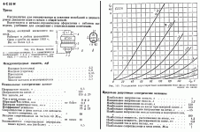
George, how do you like this beast? S=12 mA/V, u=75! 😎
Attachments
Last edited:
Missed It By That Much.....
"Sorry about that" . 😉
Dan.
EDIT: Ah this just crossed the wire a moment after Max Headroom's.....
"Sorry about that" . 😉
Dan.
Last edited:
Cathode Interface
It was discovered in tubes used for digital applications. Since they would run in digital they were either conducting or cut-off. Some bits would be off for a very long time and "stick". This isn't quite the same as "standby" since the anode voltage was present but the grid was biased off. I believe techniques were devised to deal with it (in reality they were called "transistors").
There was a great book on vacuum tube reliability published in the late 60's or early 70's. It had more real word info on how to get life from tubes than any of the other lit at the time. I last saw my copy in the late 70's so I can't give more info on it but someone else may have it.
The late Allen Wright describes one thus in his Tube Preamp Cookbook. As I recall, about the only problem i noticed was his assumption that the load presented to the JFET drain by the common-grid tube is sufficiently low impedance, and the transconductance of the JFET sufficiently high, even when he's going for maximum gain out of the circuit presented. I have forgotten what the parts were, but I think I know where the book is in storage.
He was kind enough to sell me one of his last copies some years ago, and waxed rhapsodically about the degrees of freedom one would surely have at a big company like my then-client Harman. I was rather sad to tell him this was illusory, at least for them.
Hi,
The mentioned configuration appears on the late Allen's website, on the schematic pages, in various models of preamps.
Allen cascoded JFETs or BJTs with 6922/E88CC tubes. I'm going to try it with triode strapped D3a and transformer output, instead of anode resistor and output capacitor.
how do you like this beast? S=12 mA/V, u=75! 😎
Keep away
 , it is red 😀
George
'Getting the most out of vacuum tubes'? I forget the author's name. I'm sure Google can help - I think I have a paper copy somewhere but it is also available online.1audio said:There was a great book on vacuum tube reliability published in the late 60's or early 70's.
I never cease to be amazed at the discussion here. DC in transformers? Barkhausen noise? Low level low frequency distortion? Shot noise?
Has anybody studied these things? I don't know where to start.
The quickest way to increase the distortion of a low level transformer is some DC leakage in the primary or secondary. Actually demagnetizing the transformer is important if it may have been magnetized for some reason. That requires driving the transformer to saturation and then reducing the drive to zero.
This relates to the all too common problem with toroid power transformers and blowing fuses. Often the transformer had power removed while the current was at a peak. That leaves the core saturated and the inductance close to zero. Translates to a short (primary DCR) on powerup and the resultant current (100's of amps) popping the fuse.
'Getting the most out of vacuum tubes'? I forget the author's name. I'm sure Google can help - I think I have a paper copy somewhere but it is also available online.
Good hit. And free to read: http://ia700200.us.archive.org/10/i...GettingTheMostOutOfVacuumTubes-Tomer_text.pdf
Good hit. And free to read: http://ia700200.us.archive.org/10/i...GettingTheMostOutOfVacuumTubes-Tomer_text.pdf
That's a fascinating book. I was looking forward to the mention of "picture tube boosters" and there it was.
I must say that if one were to read this early on it might dissuade from using tubes at all!
In the discussion of interface resistance, I was reminded of a tube that Qvortrup prizes, the 6463, which was evidently developed for digital applications. My friend got some GE ones, and was told that they were the worst brand for that type but still pretty good. Evidently the favored ones were Philips or maybe it was Telefunken.
I tested a few of the tubes hoping that the preference might be reflected in constancy of mu, but they didn't seem to be all that good.
That's not a technique familiar to me. We use damped sinusoids, where peak would be saturation. Or, just go over curie.The quickest way to increase the distortion of a low level transformer is some DC leakage in the primary or secondary. Actually demagnetizing the transformer is important if it may have been magnetized for some reason. That requires driving the transformer to saturation and then reducing the drive to zero.
This relates to the all too common problem with toroid power transformers and blowing fuses. Often the transformer had power removed while the current was at a peak. That leaves the core saturated and the inductance close to zero. Translates to a short (primary DCR) on powerup and the resultant current (100's of amps) popping the fuse.
Magnetic saturation is typically in the 1.2 to 1.5 tesla range for lots of core material. Coercivity of good magnet steel is typically in the 80 A/m range, after exposure to >10,000 A/m.
The remnant field isn't anywhere near saturation, but more than 2 orders of magnitude down.
Where did you get this information from?
jn
And I'm asking you for technical writing assistance...Here's question 14 in the competency test I give all candidates for a lab position in my group.
What was I thinking??😕
jn
Perhaps bipolar digital will make the gods happy - with only the most fleeting transits through the zero state 🙂
p.s. Even better class A bipolar digital
that is ecl isnt it?
Let me say, Demian, that I appreciate your input of tubes and transformers. I have always been interested in PRACTICAL understanding and techniques relative to demagnetization of transformers.
Another 'lost' concept is 'cathode poisoning' due to keeping filaments continuously lit.
Another 'lost' concept is 'cathode poisoning' due to keeping filaments continuously lit.
Since it's discussed in detail in "Valve Amplifiers," the most popular current book on tubes, and it's been discussed in multiple threads here, in what way is that a "lost concept"?
What I like about Skov's article is: It is based on both practical experience and engineering practice. Yes, it was written almost 50 years ago, when I was only 12, and most here were in diapers or not even born yet. Still, this article is relatively complete, researched, and gives practical 'tradeoffs' especially for vacuum tube circuits. The MR-70 was one of the last of the really sophisticated audio tube designs. By the time that I started working for Ampex, about 3 years after this paper was written, I could not find a single tube available for design.
Still, the MR-70 was ALWAYS considered superior to the AG-440 or the MM1000 electronics. So much for progress and 'fashion'. '-)
Still, the MR-70 was ALWAYS considered superior to the AG-440 or the MM1000 electronics. So much for progress and 'fashion'. '-)
SY, I knew about 'cathode poisoning' but it is interesting to know the 'why' of 'cathode poisoning' that makes sense.
Tubes are not my forte. Let's switch to jfets, if you wish to debate.
Tubes are not my forte. Let's switch to jfets, if you wish to debate.

That's not a technique familiar to me.
Same basic technique for demagnetizing things like tape heads or magnetic tape. Hit it with a high level, low frequency magnetic field and gradually reduce it to zero. The domains "stick" in random directions leaving no net magnetization.
se
- Status
- Not open for further replies.
- Home
- Member Areas
- The Lounge
- John Curl's Blowtorch preamplifier part II