Many of my colleagues would MARK their records and CD's for polarity. It is about 50:50, because it is usually ignored in the recording process. Sometimes, some mikes are in polarity and some mikes are reverse polarity and with multiple mikes it can get confusing as to which ultimate polarity one might want to listen to the selection.
Someday, I hope to show how the late Jim B. 'solved' this problem, one that I could only correct with relays.
Sumo 9? he used the op-amp in-amp confiuration with different gain resistors on each side, the common-mode gain stays 1 and the differential outputs can be exactly complimentary.
You mean on the input JFETs, something like this?
I'd expect lower input capacitance, but possible stability problems. Haven't a clue about the effects on open loop gain and linearity.😕 Anybody else can shed some light?
Ok. Like the Borberly all Jfet linestage. I think I prefer the sound(no stoning please) of a standard type cascode over the self biased Jfet version. It also seems to open up more opportunity for tweaking through modulation.
Even Dr. Lipshitz has been a believer in 'absolute polarity'.
Under a very restricted set of conditions, yes. Ditto Dr. Greiner, who published the definitive paper on the subject. Even your old friend Peter Aczel agrees. But the stuff that the Wood Effect guy says is, ummmm, not exactly supported by evidence.
It seems that John has brought up one of the most interesting problems with absolute polarity, that being multiple microphones and outboard equipment used during the recording process. What are you going to do when different instruments have been recorded in opposite polarity? In that instance is there a correct polarity or do you chose based on the vocal track or one of the bass instruments to have the most impact-full low frequency response. I remember in PA applications that we had a polarity checker to make sure all the cabinets were in phase but not much beyond that.
ummmm, not exactly supported by evidence.
Afair, his evidential support was that one should read the (his) book.
I tried reading one of his articles in Positive Feedback and was overwhelmed by the odor of the steaming heaps. I moved on to one of Kevin Kennedy's fine articles and sighed with relief.
Ok. Like the Borberly all Jfet linestage. I think I prefer the sound(no stoning please) of a standard type cascode over the self biased Jfet version. It also seems to open up more opportunity for tweaking through modulation.
One detail which is rarely discussed if at all: some imagine that the added device causes the drain voltage of the input one to move precisely with the input gate. But this ignores the actual impedance at the added device's source, which is no less than the reciprocal of its own transconductance and that only when the added device's drain is a.c.-grounded. When it moves as it usually does, the input device sees even a higher impedance at its drain and consequently there is less reduction of the input device drain-gate capacitance as well as other usually deleterious effects.
Although I don't like the parasitic body diode in DMOS parts, using one for the added device in the cascode looks to provide better performance than a usual go-to JFET like the 2SK246 (Erno's favorite for N-channel cascoding) or a JFET from the 2N4391 family. The DMOS has to either be a depletion-mode device (unavailable afaik in P-channel versions) or one has to contrive a bias source of several volts, for which photovoltaic optocouplers can work well. And of course there are bipolars, which need as well a little base current.
But these combinations can work well to reduce input capacitances and their voltage dependencies. Of course if your source impedance is low these are generally negligible contributions to distortions.
I also like the separated casode connection. The ability to change the voltage is nice and also quite audibly sometimes.
The DMOS has to either be a depletion-mode device.
Mr Wood,
can you give an example of a suitable suspect ?
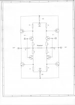
Here is how we can easily bias a 4Q ckt:
The bias resistor(s) R1,2,3,4 in this example are perhaps best at about 20 ohms. This is done by getting a graph of I output current vs V bias. Note that both the P and the N devices will 'track' pretty closely.
The bias resistor(s) R1,2,3,4 in this example are perhaps best at about 20 ohms. This is done by getting a graph of I output current vs V bias. Note that both the P and the N devices will 'track' pretty closely.
Attachments
One detail which is rarely discussed if at all: some imagine that the added device causes the drain voltage of the input one to move precisely with the input gate. But this ignores the actual impedance at the added device's source, which is no less than the reciprocal of its own transconductance and that only when the added device's drain is a.c.-grounded. When it moves as it usually does, the input device sees even a higher impedance at its drain and consequently there is less reduction of the input device drain-gate capacitance as well as other usually deleterious effects.
Although I don't like the parasitic body diode in DMOS parts, using one for the added device in the cascode looks to provide better performance than a usual go-to JFET like the 2SK246 (Erno's favorite for N-channel cascoding) or a JFET from the 2N4391 family. The DMOS has to either be a depletion-mode device (unavailable afaik in P-channel versions) or one has to contrive a bias source of several volts, for which photovoltaic optocouplers can work well. And of course there are bipolars, which need as well a little base current.
But these combinations can work well to reduce input capacitances and their voltage dependencies. Of course if your source impedance is low these are generally negligible contributions to distortions.
Thank you for the info. What makes a depletion mode DMOS more attractive(if it is) than traditional cascode using bjt or mosfet.
Mr Wood,
can you give an example of a suitable suspect ?
There are a few. The ones Walt likes are made by Supertex. But I think someone mentioned an Infineon part.
Here is one of the supertex ones: http://www.supertex.com/pdf/datasheets/DN2540.pdf
You guys are 'barking up the wrong tree'. The Supertex depletion mode devices are OK for N only cascoding, BUT they will not do the P side. It is better to use HI Idss analog switch parts like the j111 and the j174, that are American parts from several manufacturers.
What makes a depletion mode DMOS more attractive(if it is) than traditional cascode using bjt or mosfet.
The depletion mode part will not require additional positive bias on the gate relative to the source. Thus the lower "input" part will see a few volts if the upper "cascode" part's gate is tied to the lower part's source. This is how virtually all JFETs work, i.e. they require (for N channel parts) a negative gate-source voltage to turn off, and are otherwise normally on.
Typically, DMOS is enhancement mode, so we must provide a gate-source "on" voltage in addition to what we want the lower "input " part to see at its drain. A bipolar will also need base-emitter forward bias in addition to the desired lower device's drain-source voltage, and the bipolar needs a litttle base current as well.
These higher-transconductance parts are going to provide a lower impedance to the lower device drain, when hooked up in the common-control-electrode mode (common-gate or common-base). Thus the Miller multiplication effect of input device drain-to-gate capacitance will be closer to unity for the fixed-bias upper device, and closer to zero for the bootstrapped version.
The motivation for bootstrapping is not merely to reduce capacitance per se, but to reduce the voltage dependence of that capacitance and thus the distortion it may introduce.
Bcarso, while high Gm is not a bad thing, it also tends toward low Vp and this is not so good. That is why, we tend to use very high Idss-medium Gm devices in order to get a greater Vp so that the input device operates more like a real jfet.
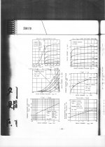
DN2540
Transconductance of 325mS at 120mA, but far less pretty under 10mA drain current.
Two K170GR in parallel would have an impedance under 25R, with J74 available.
(a relic like me still has a bundle of Grey J72/K147, and diy folks can still opt to locate NOS complementary parts with high gm numbers, as e.g. J104/K364)
Bcarso, while high Gm is not a bad thing, it also tends toward low Vp and this is not so good. That is why, we tend to use very high Idss-medium Gm devices in order to get a greater Vp so that the input device operates more like a real jfet.
The questions still bugs me a little. What advantage does a self biased Jfet have over high gain BJT? They are plentiful with low noise figures, whereas Jfets are basically impossible to find with needed spces, especially when considering complimentary arrangements. With the bjt's, are we worried about resistor noise, like in a phono stage?
- Status
- Not open for further replies.
- Home
- Member Areas
- The Lounge
- John Curl's Blowtorch preamplifier part II