Cascodes? What was the advantage of breaking up middle resistor into 4 resistors plu pot. I can see the pot for adjustment of contribution of each half, but why split the others? I like being the only guy that doesnt know.
Last edited:


Cascodes?
That's one way, but I think that would take more than 4 more parts. I also think there's a better way. Let's see if John has gone there yet.
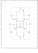
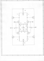
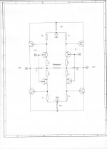
Of course there is the 'folded cascode version, which I use with Vendetta and the CTC Blowtorch, but it is actually easier to look at this basic (not primitive) version of the 4Q input stage, and learn what each of the resistor sets do. Here, for example, is a more typical approach that I use with Parasound and Constellation.
First the original, second the typical:
First the original, second the typical:
Attachments
Buzzforb, your questions are revealing.
First, some resistors give feedback, others give bias, some do both. The only obvious resistor function on the input is the variable pot.
It can, acting alone, control the total current of the entire 4 devices, forcing the n channel pair current to match the p channel pair current, due to the fact that there is no ground reference, and the only place for the current in all 4 devices to flow, is with the variable pot, YET the bias pot is not really necessary, just a convenience.
(By the way, I will talk about locally connected cascodes later, SY.)
I have never heard the device being criticized at this time. I have no opinion of it, at this time.
You're right. I misread what you wrote. My apologies.
se
Here is the 'minimum' version for discussion at the moment:
Does this version contain feedback or is it just another way of loading the output?
Attachments
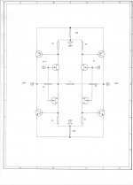
This version uses the 1K 'load' resistors also as feedback resistors.
What is missing is the BIAS resistors. This simple design runs on the Idss of the input devices and there is NO control their current, so extreme selection would be necessary if we used the design this way, BUT it is the most simple way to show it in full 4 Quadrant symmetry.
What is missing is the BIAS resistors. This simple design runs on the Idss of the input devices and there is NO control their current, so extreme selection would be necessary if we used the design this way, BUT it is the most simple way to show it in full 4 Quadrant symmetry.
Last edited:

congratulations on the constructive conversation John and getting it back on track after the mention of an all permeating localized quantum audiophile atmosphere generation device....
As some may note, the 4Q design is both flexible, yet subtle in how it can be biased and stabilized. There are a number of more variations in the second stage and even adding a follower, but that only complicates the topology, and does not add to it.
Might be interesting to know how you handle the DC offset issue as the N and P ch (dual?) JFETs are, even though Idss-matched, not identical gm wise.
Another trim pot ?
Another trim pot ?
Here is the CTC Blowtorch way of input current control:
JC-80 / JC 2
The outputs are servoed. Please take a look at the schematics JC put up a few pages back.
Roar
The outputs are servoed. Please take a look at the schematics JC put up a few pages back.
Roar
You can also use a switch that's enclosed to prevent junk from getting at the contacts.
se
SE, yes that's what I'm thinking about as well... is your switch case self made or which company offers such switches?
Yes, but a servo is not supposed to fix these types of DC offset issues. A servo is there to take care of long term drift and temperature drift, IMHO.
The outputs are servoed. Please take a look at the schematics JC put up a few pages back.
Roar
There are techniques to balance Gm, if necessary. However, the usual way is to get Gm 'matched' complementary diff pairs in advance, such as the 2SK389, 2SJ109 combination.
If you start with these, you are WAY AHEAD.
If you start with these, you are WAY AHEAD.
Who is the author of Parasound PLD-2000 power supply and regulators? A very simple zener referenced series regulators.
Having looked JC-2 high res. photos, I think that it uses the same single stage regulators. Raw PS is dual bridge , but not dual mono, similar to PLD-2000.
Having looked JC-2 high res. photos, I think that it uses the same single stage regulators. Raw PS is dual bridge , but not dual mono, similar to PLD-2000.
Here is the CTC Blowtorch way of input current control:
I had no way of adding the source resistors, but mentally, they were there. I am interested to see the progression.
SE, yes that's what I'm thinking about as well... is your switch case self made or which company offers such switches?
I get them from Acoustic Dimension over in the Netherlands.
Acoustic-Dimension, high-end audio and components for tube audio
se
- Status
- Not open for further replies.
- Home
- Member Areas
- The Lounge
- John Curl's Blowtorch preamplifier part II