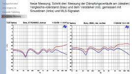
Trying to read through the article (my German is zilch) I think they say there is a difference between sine wave and MLS measurements. That is true and easily explained- the sine wave measurement uses a wide band detector so harmonics will add with the fundamental, the MLS is intrinsically narrow band, it needs to be to derive the individual frequency response. Further the MLS system is band limited by the A to D and D to A conversions.
After that I really could not make sense of the article.
If I can understand their measurement process I could duplicate it and see if I can get the same results.
My German is (slightly) better and I *think* I understand what they try to do, based on the pic below. It appears they excite the speaker with an MLS, and 'ground' the return side either through a resistor to gnd, or through the Zout of an auxiliary amp (that assumedly is not driven) via the switch. If the amp is ideal, there will be no signal to the analyzer. However, the amp is not ideal; for one it will exhibit rising Zout with freq which shows up as a rising curve on the analyzer.
In case of the resistor, the 'Zout' of the resistor is constant with freq so the curve is flat.
What I am not able to find out is the value of the resistor, and that is crucial. By manipulating that resistor value you can get almost any curve you want. Especially later when they normalize the curves to the resistor curve, not knowing the actual R value makes the results pretty meaningless.
jd
Attachments
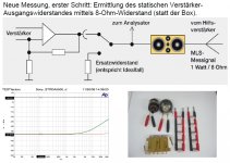
Then why does the top line read : 8 Ohm resistor instead (statt) of the loudspeaker.
Replacement (ersatz) resistor would imply just that : 8 Ohm.
Replacement (ersatz) resistor would imply just that : 8 Ohm.
i tryed to phone Mr.Schüller several times to get more details but sofar no luck. I will try again on monday.
Then why does the top line read : 8 Ohm resistor instead (statt) of the loudspeaker.
Replacement (ersatz) resistor would imply just that : 8 Ohm.
I know Jacco, that I don't understand either. If we would assume that they load the amp with either the R or the speaker, driving the speaker with the MLS doesn't make sense, at least to me.
It is also not absolutely clear to me how the switch is connected; what is the pole, what are the throws? It is ambiguous for me.
This is probably one of those presentations that really need the narrative to make sense.
jd
If you look at slide 17, it seems to imply that they drive the speaker at one terminal, and at the other terminal terminate it with either an R or the Zout of an amp. That then gives the two curves. It would make sense if the R was, in value, comparable to the amp Zout, but certainly not if R was 8 ohms.
Anybody can enlighten me here?
jd
Anybody can enlighten me here?
jd
Attachments
Mr. Evil's JFET RIAA
I refer back to post #4812 :
http://www.diyaudio.com/forums/anal...orch-preamplifier-part-ii-97.html#post2228265
Here is the schematics of a MC version as described with drift problems.
The schematics is correct except for that 2SK389's were replaced by 2SK170GR's matched pairs, and 2SJ109's replaced by 2SJ74 matched pairs.
This was something I did in 2005, 2 years after I started DIY. I know I would do it differently today, but I post it anyway for the sake of discussions. So don't drill on the stupidity of the circuit as posted.
I cascoded the 1st stage in an attempt to reduce input capacitance due to Miller effects of the large single stage gain.
The WORD picture is actually exported from ACAD and the conversion is not perfect. But if you open it in word and blow up the magnification, you can actually see all details including component values. It will be a LOT worse in PDF.
Patrick
Attachments
Constructors wondering about assembling matched JFETs into a long-thermal time constant module may enjoy Jim William's application note AN124 at LT. He shows a pair of K369s epoxy-moulded into the cap of an apple-juice bottle, in a note aimed at measuring sub-uV noise levels in voltage references. The general construction techniques Jim uses are, as usual, works for admiration.
http://cds.linear.com/docs/Application Note/an124f.pdf
.
http://cds.linear.com/docs/Application Note/an124f.pdf
.
Luckily we have something a little bit more elegant than an apple juice bottle :
http://www.diyaudio.com/forums/solid-state/135154-next-best-thing-2sk389-2sj109.html
😉
Patrick
http://www.diyaudio.com/forums/solid-state/135154-next-best-thing-2sk389-2sj109.html
😉
Patrick
John,
You have email.
Going back to the simple phono circuit, if I stick to Mr. Evils circuit for MM carts,
http://www.diyaudio.com/forums/anal...orch-preamplifier-part-ii-97.html#post2227434
but add a MC stage up front, how would you do the MC stage without using coupling caps ?
Something like blowtorch but double the no. of jfets ?
Patrick
Last edited:
EUVL, there is no need for an input coupling cap with jfets on the front end. A moving coil cartridge cannot produce DC, and the leakage of the jfets is very low. SOME bipolar transistor circuits could create significant bias current with potentially problematic results, but not always. The Levinson JC-1, for example, provided bias cancellation to a first order, and we had no complaints about biasing current problems.
Constructors wondering about assembling matched JFETs into a long-thermal time constant module may enjoy Jim William's application note AN124 at LT. He shows a pair of K369s epoxy-moulded into the cap of an apple-juice bottle, in a note aimed at measuring sub-uV noise levels in voltage references. The general construction techniques Jim uses are, as usual, works for admiration.
http://cds.linear.com/docs/Application Note/an124f.pdf
.
It's always nice to wade through all the subtle stuff but in the end floating a low noise preamp & A to D on the reference and doing all the signal processing in the digital domain would get the job done. Quantec had an excess noise fixture (noise on top of a 10V DC) that used ordinary off the shelf components.
One colleague of mine, who uses 2SK389's for a very low noise front end, uses 2 pairs of these devices with the same DC offset, and then mates them face-to-face for virtually 0 offset. He then adds thermal shielding to keep any change in temperature from effecting the readings to below perhaps 100 seconds or better.
"He singeth a quiet song"
Brilliant! I love him!
H&H and Jim's book jostled for shelf space ...
Brilliant! I love him!
H&H and Jim's book jostled for shelf space ...
It's always nice to wade through all the subtle stuff but in the end floating a low noise preamp & A to D on the reference and doing all the signal processing in the digital domain would get the job done. Quantec had an excess noise fixture (noise on top of a 10V DC) that used ordinary off the shelf components.
Scott,
Nice to see you again.
So now that I have to buy 64 bit computers, does that mean we will soon be getting 64 bit a/d's and d/a's?
I can only imagine how good they will sound!
🙂
ES
The Blowtorch as a preamp is 130 watts . . . really?!?
"the unit draws over 300W on turnon and then a steady 130W in use"
-
A headphone out would be another 130 watts? And another 100 lbs??? lol
.
"the unit draws over 300W on turnon and then a steady 130W in use"
-
A headphone out would be another 130 watts? And another 100 lbs??? lol
.
Last edited:
Less than 30W continuous, which is plenty already, considering the absence of volume/source switching current.
Scott,
Nice to see you again.
So now that I have to buy 64 bit computers, does that mean we will soon be getting 64 bit a/d's and d/a's?
I can only imagine how good they will sound! 🙂 ES
Sorry Scott,
I thought I gave you a nice straight line. But for those who didn't get the joke at 64 bits you can go from the thermal noise level of a 150 ohm resistor at room temp to the energy required to remove the atmospheres of all the planets in the solar system and still have some oomph left!
ES
Well, back to the real world. The Blowtorch preamp is like an expensive automobile. If you can't afford the electricity, don't buy it. Why does it take so much current for a 'simple' preamplifier stage? This is because we want the amplification to be as effortless as possible, just like a high torque engine in responding to a change in conditions.
A secondary factor, especially for the phono stage, when included, is for lowest noise from the paralleled jfets on the input.
A secondary factor, especially for the phono stage, when included, is for lowest noise from the paralleled jfets on the input.
Sorry Scott,
I thought I gave you a nice straight line. But for those who didn't get the joke at 64 bits you can go from the thermal noise level of a 150 ohm resistor at room temp to the energy required to remove the atmospheres of all the planets in the solar system and still have some oomph left!
ES
I've been away a lot lately. I don't remember who, but one of the great tape recording gurus (Doug Sax or Keith Johnson) once said in print that it would probably take 256 bits to equal their tweeked 30ips recorders.
- Status
- Not open for further replies.
- Home
- Member Areas
- The Lounge
- John Curl's Blowtorch preamplifier part II