Hhm, when the goal is to introduce common-mode impedance, then (larger) feedthrough caps on the output (to the device to be powered) are not a good idea, IMHO. This is sort of a dilemma, since a standard shielded cable from filter to device has the same problem. Maybe it would be best to have seperated shielded boxes for filter, psu and decive all together in one bigger shielded box?1audio said:Be sure to use good feedthrough caps to get in and out of the box.
- Klaus
BTW, how does solid brass compare to solid AL in terms of shielding effectiveness
Feedthroughs work. Do not forget that you somewhere connect signal ground (0V) to the box anyway, and you have a lot of caps from +Vs and -Vs to ground anyway. Several nF of the feedthrough would not worsen the situation.
It makes no sense to design a nice box and then use long untended wires inside.
It makes no sense to design a nice box and then use long untended wires inside.
in a case of separate psu box( like blowtorch) , row psu with CRC filter ,is better put the last cap in the audio signal box(with shunt)?
nicoch46 said:
Right , this is a problem as I'm not EE ,I'm here on diyaudio, condemned to buy a kit or build good stuff like Salas shunt.....
Do you maintain the opinion then, that a psu for audio is a special kind of psu?
Jan Didden
yes ,I find no other explanation: whay if I swap on borbely design caps or diode the sound change a lot ?
ok cooking parts is not like a design....shunt can be audio psu
😉
the blowtorch psu with: 3 passive stages, then 3 active stages of regulation and noise reduction, on each channel and each supply voltage, look like hiend psu....
ok cooking parts is not like a design....shunt can be audio psu
😉
the blowtorch psu with: 3 passive stages, then 3 active stages of regulation and noise reduction, on each channel and each supply voltage, look like hiend psu....
PMA said:
You have to shield them.
1audio said:
Lots harder to do than it may seem to be. And the shielded chokes are limited in size and value. A Mu Metal shield around a power inductor may work, or it may saturate real fast if the current is high.
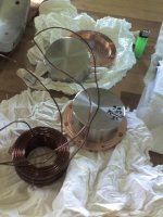
It's actually not all that to shield an inductor. With some help from Dimitri, I made a 5mH shielded inductor for a power amp PSU, some time ago.
It's a mix of ferritic stainless steel and copper shield.
Magura 🙂
Attachments
If you have long unprotected internal leads, then I recommend a cigar box lined with aluminum foil, as an adequate shield. OK, PMA?😕
PMA said:LC, if necessary.
Duh, isn't that the same as a feedthrough filter ?
Magura said:
It's actually not all that to shield an inductor. With some help from Dimitri, I made a 5mH shielded inductor for a power amp PSU, some time ago.
It's a mix of ferritic stainless steel and copper shield.
Magura 🙂
Did you characterize the effect on the inductor of shielding it? You would see the inductance change and it would have a saturation point as well. When saturated the shield effectively vanishes so you need to be sure you stay below that limit. Also it will affect the HF performance but the coil pictured will not have the best HF performance anyway.
Jacco, he was afraid of quality of a cap used in a feedthrough, so I suggested to make own with a good cap 😉
Hi Pavel,
Given the values you are looking at with a feedthrough capacitor, any low K ceramic material should be fine. Talking about power supply feeds and amplifier outputs, they are low impedance circuits, so even a high K ceramic shouldn't represent any problems. Input circuits should be easy to deal with as well. Wouldn't a length of shielded RF wire act as a feedthrough capacitor the shield was grounded at the point of entry through the casing?
I have used these off and on, usually when dealing with higher frequency circuits. RF amplifiers and switching power supplies certainly rate here.
Hi stoolpigeon, Demian,
A new thread for this would be the best. It would be a shame to confuse two designers and their ideas, and Demian deserves a thread of his own to discuss his ideas, if desired.
-Chris 🙂
Magura said:
It's actually not all that to shield an inductor. With some help from Dimitri, I made a 5mH shielded inductor for a power amp PSU, some time ago.
It's a mix of ferritic stainless steel and copper shield.
Magura 🙂
Whoa! High "sex" value to those slick lookin' shields!!
by "ferritic" do you mean non-magnetic?
_-_-bear
Edit: oh, where are we on internal PS vs. external PS, especially WRT that choke shielding issue? Do we want only DC sent through the embilical connecting cord, and what about ground if we go external??
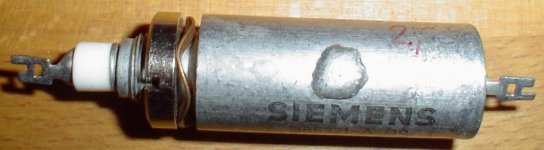
Chris, I use professional HF feedthroughs, they are also a part of my current preamp design, to clean DC PSU output wires thru an Al wall.
1audio said:
Did you characterize the effect on the inductor of shielding it? You would see the inductance change and it would have a saturation point as well. When saturated the shield effectively vanishes so you need to be sure you stay below that limit. Also it will affect the HF performance but the coil pictured will not have the best HF performance anyway.
The inductance stayed the same, due to the mix of copper and ferrittic stainless steel.
I have not had a need to push it past 10A, till that point no saturation occurred.
Magura 🙂
bear said:
Whoa! High "sex" value to those slick lookin' shields!!
by "ferritic" do you mean non-magnetic?
_-_-bear
Thanks Bear.
Ferrittic stainless steel is the type that is magnetic. It's rather rarely used, but for this it made sense.
Magura 🙂
nicoch46 said:yes ,I find no other explanation: whay if I swap on borbely design caps or diode the sound change a lot ?
ok cooking parts is not like a design....shunt can be audio psu
😉
This is an interesting question, but this is the Blowtorch thread, not the Borbely thread. Erno has some interesting design ideas, and it deserves its own thread, imho. You might want to start a thread on Borbely designs, post the schematic you are referring to, along with a jpeg of your implementation and a block diagram of your wiring/ground scheme??
_-_-bear
Magura said:
Thanks Bear.
Ferrittic stainless steel is the type that is magnetic. It's rather rarely used, but for this it made sense.
Magura 🙂
Wondering if the alloy is one of the ones with a high hardness - making it difficult to machine??
_-_-bear
- Status
- Not open for further replies.
- Home
- Member Areas
- The Lounge
- John Curl's Blowtorch preamplifier part II