If I got it correctly, all you have so far is comparison to reference amp, not anything you can learn from that shape pulsed in itself. If this is the case, that's the major drawback of your finding.
Hi Joshua,
you got the points!!
Let's do some brainstorming about...
Well, one of the major concern I always had it was why, in example, the same amp gave different sonical behaviour when inserted in different systems. When you consider the transient response to the shaped pulse you are evaluating only one component of the audio system; but, what we hear, is the combination of the transient response of every part of the audio chain. Starting from the mic, that captures the audio signal, up to the loudspeaker that reproduces that signal, there are a lot of low pass and, some less, high pass filters. Considering the overall system we have, at the end, an high order band pass filter; the transient response of this band pass filter relays on the pole-zero staggering that have been put inside the chain. Wohw!!
Well, the experienced designer (like John, Nelson, Charles) has the control of only one component (the one he designed), but the poor-man-designer (the end user) buy its components (CD player, pre, amp, loudspeakers, interconects, etc.) and makes its own design and, in most cases, without having any background on what is doing, so he can use only a, very expensive, trial and error approach: buy one component, listen to it for some time, then, if dassitisfied, he buys another one and so on...If he is very luky, with only some trials, he builds-up a good system: is it the best system? He doesn't know...so he continues to modify his chain with better and worse results.
We diyers are luky!! We could design our system with the same competence that we use to design our amp, or our loudspeakers, so we can have the opportunity to build-up a better audio system with less trials and errors. We can have the control of the transient response of our audio system.
The absolute device doesn't exist!! We live in a real world.
Last edited:
Hi Luigi,
I agree with most of what you wrote.
As for diyers being lucky, it's true with you case, with your findings about the shaped pulse. Most of us, diyers, are still bound to trial and error - that is, for those of us who choose components to the sound system by listening. Some are satisfied with known and accepted measurements.
The AP software has the options to set the phase of the tones as you wish. In phase, random or whatever angle you want. Not sure what the means to the measurements, tho.
Yes. Also you can specify the max crestfactor, to avoid unintentional overdrive. I think the two are linked; you can either lock the phases or limit the crest factor. Need to look up the details.
BTW You can just download the AP software and play with it, and generate a list of frequencies and levels and phases for use in other apps if you are interested.
jan didden
You can generate a range of crest factors with a given set of tones, the max is all in phase but that just looks sinc-like. I don't know if the min is solveable in closed form. Gaussian noise has an expected crest factor depending on BW and time interval, this can be computed.
[I don't know if the min is solveable in closed form. Gaussian noise has an expected crest factor depending on BW and time[snip] interval, this can be computed.
Apparently not; the makewave.exe gui lets you tick the box for minimum crest factor and then a numerical value for a # of tries. The phase relationships are randomized for the specified number of tries, and the best solution is retained.
The stand-alone app called makewave.exe can be downloaded from the AP website, last time I looked.
jan didden
Yes, random search not a direct computation. It can be done with a "thermal" annealing algorithm which works well for a lot of tones.
As an asside the minimum crest factor is an interesting problem, obviously it can't be zero.
Last edited:
lvigone, can you post some of the pulse measurements you did ?
For example, the response of the "reference" amplifier, one for a similar sounding amplifier and one for a bad sounding amplifier ?
Thanks.
Fireworks,
my measurements could be of no value for you: they are the measurements of the best sounding amplifier in my system. In another system, the results could be completely differents.
The design of an audio reproduction system is like working with a kitchen prescription: the final result don't depend from a single ingredient, but from the sage mixture of all the ingredients.
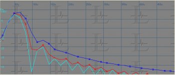
Anyway, in attach you will see the three step "tuning" I made on my amp to arrive at the final best configuration. The light blue curve is the reference and the actual situation, the blue the starting point and the red the second trial. Moving from the blue curve to the light blue curve, the low frequencies became more defined and punchy, the middle more detailed and the high more aired: the image became more focused and solid rock.
What I suggest you it's to experiment: start from your amp, measure the pulse response, change this response in one direction then in the other and listen to the results. You will learn how to manage the sound!! I'm sorry, an absolute transient response doesn't exist: there are too many elements involved in an audio system.
Another hint: you have to find the actual "limiting" element of your audio chain. In my experience it alway exists. At first, make the pulse measurement of every single component (i.e., pre-amp, power-amp, CD player, phono stage, interconnects, etc.), then make the pulse response of the complete chain and look at the result; you should study carefully the complete transient response to identify which is the limiting element. Then, start to work on this one. When you will be satisfied, repeat the complete process and do the same on the new limiting element. The improvement margin is great.
You will be astonished from the change on the sound you will gain without making any change to the "traditional" distortion figures.
Have fun!!
Attachments
Thanks for the details !
I am aware that your results will not be useful for other systems but I'm just curious to see different pulse responses and the associated sound "qualities".
On your graph, can you also show the input pulse ? Is it a Dirac, Gaussian or something else ?
Another question: what software you used for measuring the pulse response ?
The light blue curve is the reference and the actual situation, the blue the starting point and the red the second trial. Moving from the blue curve to the light blue curve, the low frequencies became more defined and punchy, the middle more detailed and the high more aired: the image became more focused and solid rock.
Could you, please, tell us, what measured did you implement for getting from the blue curve to the red curve?
Did these measures really not affect THD and IMD figures?
Last edited:
On your graph, can you also show the input pulse ? Is it a Dirac, Gaussian or something else ?
You can see the input pulse on post #14631, on page 1464 of this thread. It's a raised cosine low-pass filtered at 24KHz.
Another question: what software you used for measuring the pulse response ?
Actually I use Praxis, but an high performance storage scope works fine too.
Last edited:
Could you, please, tell us, what measured did you implement for getting from the blue curve to the red curve?
Did these measures really not affect THD and IMD figures?
I changed the value of the capacitor that creates the circuit dominant pole: passing from blue to light blue its value was decreased (by the chance, this amp is a NO NFB design, so this modification didn't affected the circuit stability). The transient response is related to the transfer function of the amp, so to change the pulse response the transfer function of the amp+power supply+layout parasitics capacitances and inductances has to be managed.
Luigi, this is most interesting. I use pulses to measure speakers for many years. Amps i usually measure with square wave but i never had the idea to copy another amp that sounds good in a particular system. My idea was more that the amp should be "transparent". The question now for me is : what is the pulse response of an amp that is audibly transparent ? when i measure speakers i use a somewhat different method. I use the Step Response. In theory this is a sharp ramp. Like connecting a battery to the speaker. When the speaker is totally flat and minimum phase from DC to light the response should simply look like a ramp. So jumping up straight and staying there. This is of cause physically not possible unless you use a fan. See the Step Response of my main speaker. It is a wideband driver on a baffle, high pass filtered at ca.80Hz. In the bass i use an active M-Dipole. The response is basically phase linear.
Attachments
I changed the value of the capacitor that creates the circuit dominant pole: passing from blue to light blue its value was decreased (by the chance, this amp is a NO NFB design, so this modification didn't affected the circuit stability). The transient response is related to the transfer function of the amp, so to change the pulse response the transfer function of the amp+power supply+layout parasitics capacitances and inductances has to be managed.
I have a feeling, that improving the pulse responce according to your approach, is similar to obtaining correct square-wave responce at 500kHz.
The amp, giving nice 500kHz square wave, will do your pulse also.
Amps i usually measure with square wave but i never had the idea to copy another amp that sounds good in a particular system. My idea was more that the amp should be "transparent". The question now for me is : what is the pulse response of an amp that is audibly transparent ?
Joachim,
I stay away from repetitive stationary signals, because they don't give any usefull information, at least from the sonic point of view. These signals are ok to check stability, static distortions and so on, but they are useless to unveil the "sonic DNA" of any audio device.
Regarding your question I don't have any answer. Joachim, do you own Dennis Feucht Analog Circuit Design book? If no, I suggest to look for a copy: it's light on analog circuits design.
In Feucht book you will learn that identical amplifier stage, when cascaded, don't have the same characteristics as a single stage, so why make an effort to design a "transparent" amp: when it will be inserted in any audio chain, it will have little chances to contribute to the "transparency". But I can understood your concern: it's the concern of any good audio professional designer.
I'm a diyer, and I have to please only myself, so I'm luky!! I can design the "transparent" audio system; I think this should be a little more easy.🙂 The transparent audio system is the one with the transient response more similar to the input pulse, but...wait!! What about the transient response of the recording chain? Forget it!! You will loose your sleep!!
The life is full of compromises; you have to look for the best compromise. I'm strongly convinced that doesn't exist a "real" audio device that can be defined "ideal" and it can be used to play all the existing musical software in a transparent way. The transient response of your best ideal audio system will be combined with the transient response of the recording chain, that will change from recording to recording, and the total transient response will have the chance to stay transparent, maybe, only in one case over a million!!
when i measure speakers i use a somewhat different method. I use the Step Response. In theory this is a sharp ramp. Like connecting a battery to the speaker. When the speaker is totally flat and minimum phase from DC to light the response should simply look like a ramp. So jumping up straight and staying there. This is of cause physically not possible unless you use a fan. See the Step Response of my main speaker. It is a wideband driver on a baffle, high pass filtered at ca.80Hz. In the bass i use an active M-Dipole. The response is basically phase linear.
Step response is another way to get the loudspeakers transient response: it's one of my preferred test for loudspeakers. From more than 20 years I use only fullrange electrostatic speakers because they have one of the best transient response. Of course, they are dipole!! 😉
The step response of your speaker looks very good.
P.S.: by the way, I was born in 1957, too 😉
I have a feeling, that improving the pulse responce according to your approach, is similar to obtaining correct square-wave responce at 500kHz.
The amp, giving nice 500kHz square wave, will do your pulse also.
No, I don't think so, Vladimir. My amp has only a 85 KHz -3dB corner, so it will not be able to reproduce a perfect 500 KHz square wave.
Ivigone you explained your point of view very well. You are maybe only a DIY´r but you certainly know what you do and what you like. Hats off.
Interesting stuff. I think also that the single, non repetitive pulse, may be an important 'key' to further enlightenment.
It seems, You was simply changing BW of your amplifier. More BW= more details (mids, "airy" treble), speed(bass attack). Red curve pulse response shows "something" band limited well inside audio band (if time axis in meausurement is correct)...I changed the value of the capacitor that creates the circuit dominant pole: passing from blue to light blue its value was decreased (by the chance, this amp is a NO NFB design, so this modification didn't affected the circuit stability).
Last edited:
- Status
- Not open for further replies.
- Home
- Member Areas
- The Lounge
- John Curl's Blowtorch preamplifier part II