I will continue with the massive paralleling approach, since I have always thought that it was the best overall way to go.
There are 2 main issues that I have always had with mc input transformers that I have to contend with, since my first Ortofon that I purchased in 1966.
One, is low frequency distortion, especially due to record warps, and the potential of IM between the warp frequencies and the rest of the music.
Second is the potential for added noise, above and beyond the DC measured resistance of the transformers, (referred to the input) due to eddy current noise produced by relatively thick laminations such as 13 mils.
Personally, I have made a breakthrough in my own design that potentially removes the need for a transformer, in any case, and I have decided to put it aside. In other words, I just don't need it to make specs.
However, for other systems, especially tube equipment, transformers to allow for quieter operation as they have for almost 100 years, especially if they are good, well made transformers, like Jensen, etc.
I will leave the rest of the discussion to others, at the moment.
Did you run into any oscilation problems when you paralleled the Fets ?
The figure of merit is too low on the Toshiba JFET's, The BF862's easily oscillate when paralleled > 4.
When I get a chance I will draw a picture of my setup.
I got in trouble when i paralleled 7 2SK170 and 6 2SJ74 for a total of 13. Of cause it can be taken care of with coils in the gate feeds but some do not like ferite coils in the signal path.
It´s a parallel symmetric design. The Fets work on constant current sources. Then there
are folded BJT cascodes. I took 7 and 6 to equalise Gm somewhat. I could not make it work without coils.
are folded BJT cascodes. I took 7 and 6 to equalise Gm somewhat. I could not make it work without coils.
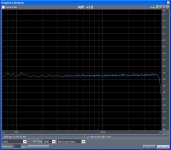
Just a quick one today, cheap throwaway Chinese 10:1 mic transformer loaded with 200 Ohms and looking at the open loop noise in the primary. Quite a different story. Looks like 6K rather than 20K (6dB less noise) and verified the 10:1 'ness of it???, but there is no extra noise.
Attachments
Last edited:
I might also disagree a little on this, yes eddy currents are a loss but it is not a given that they generate excess noise (coupled back into the system) especially in a fairly pure conductor.
Aha, I finally found it...
Low fat milk, no sugar...no zip-loc..
Cheers, John
Bob: For a bipolar input, the input xfrmr will probably not be optimum since noise figure is minimized at Rsource = en/in. For FETs and tubes, the transformer will almost certainly give a noise advantage for low Z MCs- in fact, it can reduce the need for massive paralleling. The issue of CMR is another reason why one would want to go that route.
John C has speculated that there's an intractable LF noise source in step up transformers. I haven't seen that in actual MC amp noise measurements, but the Smart Guys are now doing some other measurements to see if it's plausible and under what circumstances it COULD be significant.
Hi Sy,
Thanks for your response. So I guess this discussion was sparked by a transformer-vs-solid state MC step-up noise issue.
I understand about the BJT input - you are referring to the input stage of the RIAA phono preamp. My take would be not to use BJTs on the input of the RIAA phono preamp anyway. I'm already assuming JFETs there, although I realize some would differ.
I also believe that JFETs are even preferable to BJTs as the input stage of the head amp, even though they need some paralleling. I admit it is harder to make the case there, at least based only on noise performance. However, I think JFETs will be significantly better in susceptibility to EMI. If JFETs sound better overall as the input device in a head amp, AND their noise is good enough, this would be an example of where too much focus on extreme low noise might not yield the best preamp.
Along these lines, it is instructive to look at the tradeoff for the RIAA phono preamp. Let's confine the discussion to JFET inputs. We can get low enough noise with a single JFET at this point in the system. However, we can get lower noise by doing lots of paralleling. Should we? Not necessarily, because we need to watch JFET input capacitance. If we do a lot of parelleling for the JFET RIAA phono stage just to be able to brag about unnecessarily low noise, we may thus jeopardize other areas that influence sound quality.
Cheers,
Bob
Noise like 6K, don't have extra time today but will check it out. The interesting thing is the lack of frequency dependent component (even if there was a 6dB loss).Do you mean measures impedance like 6k, or generates noise like 6k?
Aha, I finally found it...
Low fat milk, no sugar...no zip-loc..
Cheers, John
I thought I explained that "excess" noise in my biz means not "strictly" thermal in nature. That is GR noise, for instance, depends on trap activation energy which is highly temperature dependent. I'll buy the coffee in any case.
Last edited:
Just a quick one today, cheap throwaway Chinese 10:1 mic transformer loaded with 200 Ohms and looking at the open loop noise in the primary. Quite a different story. Looks like 6K rather than 20K (6dB less noise) and verified the 10:1 'ness of it???, but there is no extra noise.
You mean 1:10, yes? 10:1 would be a step-down, not a step-up.
se
Along these lines, it is instructive to look at the tradeoff for the RIAA phono preamp. Let's confine the discussion to JFET inputs. We can get low enough noise with a single JFET at this point in the system. However, we can get lower noise by doing lots of paralleling. Should we? Not necessarily, because we need to watch JFET input capacitance. If we do a lot of parelleling for the JFET RIAA phono stage just to be able to brag about unnecessarily low noise, we may thus jeopardize other areas that influence sound quality.
Cheers,
Bob
That is an interesting point.
Tube amp designers often warn against parallelling tubes because it might impair sound quality, whereas parallelling tubes eases transformer design and of course yields more output power. Comparable trade-off?
You mean 1:10, yes? 10:1 would be a step-down, not a step-up.
se
It's actually from in the mic (step down). Don't they go both ways, he said stupidly?
We can get low enough noise with a single JFET at this point in the system.
Can we? What's S/N for a single FET input, assuming an MC cartridge with 0.2mV reference output?
I think paralleling is necesarry in the modern market place. 0.5nV/qHz is the maximum noise if you want to win any recognition. Because i mostly design parallel symmetric i have another problem. Low noise P-Channel Fets are hard to get. On the other hand single ended can be made to work well too but when i do that i use feedback. 2nd harmonic is not that bad but simply too much for me in a single ended circuit without feedback. At least the stage i made with feedback sounded fine so i am not even an advocate of the "Zerro NFB in the first stage" school. I still have several hundred 40mS Toshiba N-Channel Fets and 4 of them in parallel gave one of the lowest noise stages i made.
Bob, where do you see the sound quality problems with paralleling ?
I on the other hand learned that a lot of different topologies can be made to sound fine when you understand how they work.
Bob, where do you see the sound quality problems with paralleling ?
I on the other hand learned that a lot of different topologies can be made to sound fine when you understand how they work.
I thought I explained that "excess" noise in my biz means not "strictly" thermal in nature. That is GR noise, for instance, depends on trap activation energy which is highly temperature dependent. I'll buy the coffee in any case.
The bet is as you say. I went too far back in the thread..man, it's way too long...
I think I have a reasonable test:
Take a reasonable transformer or inductor made with a core you can split. Preferably with rather thin laminations.
Measure the unloaded noise, resonate it, and measure Rs-Ls from 20 to 20k. If a swept sine drive can be used with an FFT to look for sidebands, go for it..
Split the core, remove the bobbin, lap all the surfaces where the lamination edges are. Re-assemble the structure with a layer of saran wrap (thinnest thing I could think of..) on the joining surfaces of the core. Verify by meter that there is no electrical continuity between magnet pieces and between laminations. re-assemble. Retest all parameters.
Pull it apart, reassemble...test...do this 5 times. In that way, you baseline the entire setup, core and all, and verify repeatability.
Now, pull it apart. Using silver epoxy, coat every surface of the core where the lamination edges are visible. This must be done on the outer edges AND the inner edges. Otherwise, no additional eddy type loops will be formed. Since they were previously lapped clean, this will form conductive loops which will be consistent with eddy current paths. Granted it is only on the edge as opposed to the bulk, but let's continue.
Re-assemble again with the saran wrap. Verify that there is no continuity core to core.
Re-test. repeat 5 times.
If a significant change in the eddy current losses were created by the silver epoxy shorts, it should show up in LS-Rs, resonance, sine with sidebands.
As to my discussion with DF96....
If the unloaded noise does not change, then this is consistent with what I have been saying regarding eddy current noise. I may be correct.
If the unloaded noise does change, then I am most certainly incorrect and DF96's assertion is definitely correct.
Cheers, John
Last edited:
- Status
- Not open for further replies.
- Home
- Member Areas
- The Lounge
- John Curl's Blowtorch preamplifier part II