That's part of the output low pass filter gimmick. It adds a cutoff at about 2 GHz to improve stability. They are individually hand tuned. Don't you use them?
Just noticed one is correct and the other has its helix reversed. That will cause problems depending on the amps orientation unless you are near the equator. . . (Like Thailand?).
Just noticed one is correct and the other has its helix reversed. That will cause problems depending on the amps orientation unless you are near the equator. . . (Like Thailand?).
Last edited:
Don't you need two for the JBLs?
Oh Sh*t. Yes. I will need two.
-RNM
what speed do you need and why?
Speed of very fast CFA to listen some favorite music and really enjoy .
Probably can do little harm, since outside loop.
Is it outside the loop?
When one has a low impedance current loop such as an output wire pair, the dominant feature for coupling will be magnetic.
To decouple a ground reference from a dipole wire pair, several things can be done.
1. Distance.
2. orthogonality by geometry.
3. Twist the low impedance pair sufficiently that each wire couples exactly 50% to the grounding wire.
4. Coaxial wire
5. stripline wire to reduce external magnetic fields.
6. Wrap the ground around the two conductors such that they both couple 50% magnetically.
This is an example of #6
John
Last edited:
I think Waly is into RF amps.
Nope. I can feel the love in the air 😀.
And I'm fine with whatever people like (topology, sound, etc...) as long as they don't claim as being the best thing since sliced bread. Which is definely the case with Mr. Marsh.
BTW, distortion performance @1KHz tell pretty much nothing about the design performance and the implementation (which dominates the measured results from 10KHz up, since that's where magnetics are showing their ugly head), 80dB or more of loop gain at LF is trivial to get. 20KHz distortion measurements are showing the true performance of both. Wait, I can hear somebody saying "you can't hear 20KHz" (this time, otherwise bandwidth in the MHz range, wideband video amplifiers (yes, RF) etc... are required for a good sound).
Otherwise, nice construction, to bad is worth nothing for the average DIYer, not having a metal shop and a thick wallet under his belt.
That's part of the output low pass filter gimmick. It adds a cutoff at about 2 GHz to improve stability. They are individually hand tuned. Don't you use them?
Just noticed one is correct and the other has its helix reversed. That will cause problems depending on the amps orientation unless you are near the equator. . . (Like Thailand?).
My experience with anything shield-like was negative sound consequences. These may not do that, but I'd want to hear with and without.
Oh Sh*t. Yes. I will need two.
-RNM
Ha! Props to Bill for noticing that... wow. I hope they weren't already taken so you can just grab an extra?
Waly,
People build Nelson's designs all day long, why couldn't they build this one? They simply won't use as fancy of an enclosure. If I'm not mistaken the circuit is posted here on DIYaudio.
People build Nelson's designs all day long, why couldn't they build this one? They simply won't use as fancy of an enclosure. If I'm not mistaken the circuit is posted here on DIYaudio.
This is what the engineering mystery is all about. I suggested first making a very high slew rate (SR) amp of ultra low distortion to see what happens. The CFA's strength area. It just sounded even better than best effort VFA. BUT, the VFA has since been tweeked to get similar results to CFA and I havent heard those. And, the CFA has been tweeked with -B to outwardly behave like VFA... so the gap is closing due to these newest efforts to compete with CFA's strength area.
The internal CFA with buffered (-) input behaves for app enginners like VFA but keeps speed up etc. Does CFA-B have improved PSRR? If so, IT maybe the design of the future for all High-End amps ---- IMHO, of course.
[-B = CFA's minus input Buffered]
I suspect the established SR estimated as adequate for audio amplifiers is too low??
THx-RNMarsh
Mr.RNMarsh
Did you have some schematic example for that specific CFA-B topology? , I`m interested ,
`I suspect the established SR estimated as adequate for audio amplifiers is too low??`
- in most of the cases is Definitely so !
btw, IMHO most of good designed and executed CFA`s deserves to be in installed as part of sound systems inside of top notch recording studios .
Last edited:
Speed of very fast CFA to listen some favorite music and really enjoy .
So, no engineering criteria then? Just subjective preference. Fine.
So, no engineering criteria then? Just subjective preference. Fine.
Well , what can I do ?, since I`m working as engineer no more , now and in recent years I have to repair broken TV`s , amps and other consumer electronics for living .
In the late 1970's I built and demonstrated at CES an amp with slew rate meters. The amp was good for 500V/uS and a full power bandwidth of 1 MHz (VFA). The meters were an embarrassment that were never implemented in production. At 500V FS they never moved on any audio. I rescaled them to 5V/uS FS and they sort of moved at the bottom of the scale. Even with Vinyl (LP's remember?) there was NO real HF content. Nor on tape from Keith Johnson's 3 track, the widest band source available at the time.
However making an amp that would behave with the high bandwidth really schools you on details, which may make a difference.
However making an amp that would behave with the high bandwidth really schools you on details, which may make a difference.
Nope. I can feel the love in the air 😀.
Otherwise, nice construction, to bad is worth nothing for the average DIYer, not having a metal shop and a thick wallet under his belt.
Yeah, right, like 90% of the comments in the Lounge. At least I'm not promoting my own crapola and not posting equipment porn "look what I have, do you like my display" pictures.
OK here is some of what I have in my metal shop...
Just one more useful tool. I do have a rule that is one must spend more on the material run through the tool than on the tool or it is not really worth it.
But to make a case like what was shown requires just a milling machine. Available used for under $2,000.00. (The cool thing about such tools is you can often resell them for what you paid or even more.) Well within some budgets. Others will have a local variant of a "Tech Shop" and can use tools by the hour.
Attachments
You can get a 3 axis CNC mill for under $2k used? That could be a great money spinner in some markets.
Getting a shop to make a handful of high finish parts is not that easy. Its actually really hard or expensive or both. Few shops are interested in tying up the machinery for one or two sets of parts with a large radius curve on one surface. I suspect that front panel was an extrusion. Cutting from a solid panel is time consuming and needs help to make it smooth. The Constellation stuff which is all CNC from solid blocks is very time consuming to make. The case is probably 1/2 of the total cost of a Constellation product.
Getting a shop to make a handful of high finish parts is not that easy. Its actually really hard or expensive or both. Few shops are interested in tying up the machinery for one or two sets of parts with a large radius curve on one surface. I suspect that front panel was an extrusion. Cutting from a solid panel is time consuming and needs help to make it smooth. The Constellation stuff which is all CNC from solid blocks is very time consuming to make. The case is probably 1/2 of the total cost of a Constellation product.

As much as is possible for this thread... stick to the topic.
Points and penalties have been handed out and insulting and off topic posts deleted.
You can get a 3 axis CNC mill for under $2k used? That could be a great money spinner in some markets.
Getting a shop to make a handful of high finish parts is not that easy. Its actually really hard or expensive or both. Few shops are interested in tying up the machinery for one or two sets of parts with a large radius curve on one surface. I suspect that front panel was an extrusion. Cutting from a solid panel is time consuming and needs help to make it smooth. The Constellation stuff which is all CNC from solid blocks is very time consuming to make. The case is probably 1/2 of the total cost of a Constellation product.
Milling machine for diy, CNC's start around $5,000. A lot of CNC equipment was made by folks who went out of business. Their stuff when not supported for the market drop in price dramatically. Much of it is not that hard to repair and maintain as they typically use standard parts. A $100,000 new CNC turret press can now be had for under $5,000.00! (If you can move it.)
I bought an orphaned CNC router for less than $5,000.00 which uses parts that are available from McMaster Carr. Works great, but we did need to change bearings and re-align it. New it was $50,000.00. Now there are newer less expensive models but 3 axis 5 HP makes it a nice toy.
The amp chassis is the way they want to build it. I have no (zero) input on that. This company has been making high quality circuits and build for 25 years. 50 employess and vertically integrated.
The circuit has been published for DIY'ers. I would like to ask and explore the design via the designer. That would be more productive than Waly's rantings etal. re CFA. I think the CFA has/had great potential to be pushed in many ways and versions which could over come some of the major problems of VFA for audio. Which it does seem to do very well. only minor psrr issue was left and that has been solved also with C-Multipliers in PS to IS and with -B mod and balanced apps.
Maybe someone has VFA just as good. Good for them. VFA isnt the challenge that CFA was for audio. Now, I think it has proved itself as a very worthy contender.
I show it here as proof of that effort by all here. And as inspiration and new ideas and designs.
Enjoy.
THx-RNMarsh
Last edited:
Agreed, the negativity really isn't doing any good.
Going down the CFA path is almost like a blast from the past for so many, it seems. It's like accepting that distortion isn't that important, ex. 1970's, except today we don't have problems making low distortion circuits sound good. So it's like giving up what took so long to learn...
But for me it's not all too hard; I'm not one to argue with results. I'm considering the use of carbon comp resistors again after the interesting physics lesson in this thread.
So, are you taking two home now?
Richard
The amp looks great.
Kudos to Damir for the ‘motor’
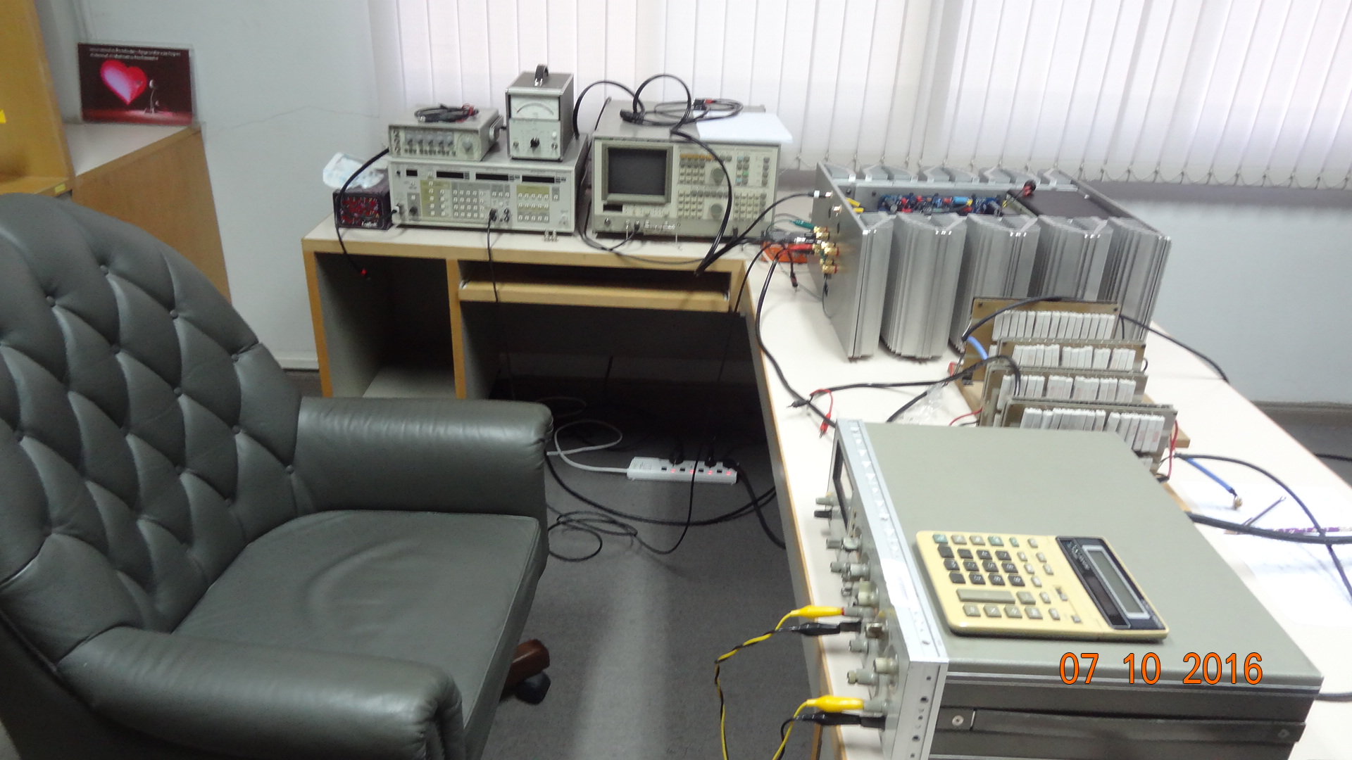
One of your next tasks would be building a proper dummy load for high power amp testing.
The dummy load shown in the picture isn’t up to the task, not for test with continuous signal at the power levels you mention.
For brief, pulse testing, maybe.
Have you monitored the R change (collectively and at each branch) due to heating from current flow?
http://www.diyaudio.com/forums/atta...s-blowtorch-preamplifier-part-ii-dsc02475.jpg
George
The amp looks great.
Kudos to Damir for the ‘motor’
One of your next tasks would be building a proper dummy load for high power amp testing.
The dummy load shown in the picture isn’t up to the task, not for test with continuous signal at the power levels you mention.
For brief, pulse testing, maybe.
Have you monitored the R change (collectively and at each branch) due to heating from current flow?
http://www.diyaudio.com/forums/atta...s-blowtorch-preamplifier-part-ii-dsc02475.jpg
George
I did a check collectively at the 2 Ohm level... no significant R change... maybe 0.1 Ohm.
I can also test with dummy speaker RLC network. Mostly interested in thd characteristics under load R changes. No need for precision measurements. THD up to clipping and monitoring output stage current into load.
Did some tests at 5 and 10KHz also. ETC.
tried three different distortion analyzers. also monitored the 230v ac line input to amp during testing. checked temp rise inside and out with IR thermal temp probe.
THx-RNMarsh
Last edited:
It might be both fun and illuminating to digitize and store that slew rate data, then whiz it through a numerical analysis software suite to compute statistics & prepare histograms. I think many people would be interested to see the density function (and cumulative distribution function) of slew rate, for five or six different tracks. What's the median slew rate? What's the 99th percentile slew rate? What's the max slew rate? etc. It would be a widely quoted, frequently referenced, authoritative source.In the late 1970's I built and demonstrated at CES an amp with slew rate meters. The amp was good for 500V/uS and a full power bandwidth of 1 MHz (VFA). The meters were an embarrassment that were never implemented in production. At 500V FS they never moved on any audio. I rescaled them to 5V/uS FS and they sort of moved at the bottom of the scale. Even with Vinyl (LP's remember?) there was NO real HF content. Nor on tape from Keith Johnson's 3 track, the widest band source available at the time.
I assume your meters presented the data in some normalized way, e.g. "Volts per microsecond, with onset of clipping @ 200W into 8 ohms" or similar choice?
- Status
- Not open for further replies.
- Home
- Member Areas
- The Lounge
- John Curl's Blowtorch preamplifier part II