Thanks for the responses. The two most common speeds are 1725 and 3450 RPM. That is due to "Slip." The moving pieces don't quite get all the way up to speed. In a more loosely coupled motor the slippage is greater.
One of the great energy usage improvements that many industrial users use is a controller to reduce the power to their electric motors based on load. These are coming down in price so they are starting to show up on consumer products.
Without a controller the motor during a single cycle draws current from the AC and then returns some of it. A circulating current. If the AC line is 3600 cycles per minute and the motor is 3450 rpm there is a sum and difference signal created. 7050 cycles per minute and 150 cycles per minute or 117.5hz and 2.5hz. A 1750 rpm motor will produce 1.25hz.
Well almost all residences have refrigerators, some have either water pumps or blower motors for heat and many have the biggest energy user of all air conditioners.
Now for the obvious question what is the effective inductance of a power transformer used in say an amplifier?
Last edited:
One of the great energy usage improvements that many industrial uses use is a controller to reduce the power to their electric motors based on load.
Pretty nice at home in the garage too.
www.diyaudio.com/forums/pass-labs/1...more-boring-making-thread-32.html#post1420424
Thanks for the responses. The two most common speeds are 1725 and 3450 RPM. That is due to "Slip." The moving pieces don't quite get all the way up to speed. In a more loosely coupled motor the slippage is greater.[snip]?
You asked for THE most common speed. That's 3600. Slippage may reduce it in practice, but I still think 3600 gets me the price.
(Of course it's 3000 RPM in 50Hz countries).
In another live (1993) I designed a micro-controller system to reduce power to the motor until the power factor was almost 1. Saves about 10-20% power. This was for a 'green plug' meant to have refrigerators and such plugged in.
The way I set it up was to monitor phase shift between mains voltage and motor current, and drive a triac to progressively reduce the conduction angle until voltage and current have no more phase shift. There were a few more goodies to handle things like sudden load increases but that was the gist of it. Worked like a charm. However, the guy I build it for got sued for infringement and that was the end of it. Yes I got paid, sort of.
jan didden
You asked for THE most common speed. That's 3600. Slippage may reduce it in practice, but I still think 3600 gets me the price.
(Of course it's 3000 RPM in 50Hz countries).
jan didden
Yes, glad you understand the issue. When that 10-20% is not being saved it modulates the power line! Just a bit.
So what happens when you put a little bit of power into a resonant load?
It continues to build up of course.
Power transformers have L and some R but it would take a lot of C to get a resonance of 2.5hz.
Anyone ever measure the resonant frequency of a power amplifier power supply with say 40 volt rails and 30,000 microfarads of C?
Steve,
There is no point to this, this thread, or life. Now that you know the true secret of life you can stop searching and move on to more productive endeavors, best of luck to you.
ES
Last edited:
Hi ES,
Anyone who took the time to measure the resonant frequency of an amp such as you proposed either has too much time on their hands, or they have ventured into an area where they are seeing problems they need to explain or solve. That's way out of anything I see, so I have zero experience there.
Now, unless that amp is at idle, varying load conditions should remove enough energy so that conditions would be too variable to simulate. It might be easier to build something like this up and watch it. Just a (total) guess.
Hiya John,
One point regarding people. Everyone is simply a person who has human faults. It is next to impossible to live up to a reputation, unless it's a bad reputation! If you place anyone on a pedestal, they will eventually fall from grace simply because they are human. So you idolized a few people who (predictably) let you down in some way.
Since you designed with microphones, you are well aware of how this works in reverse. So are every clandestine organizations in the world, and people who record sounds in nature.
Hi Scott,
He inspired me to build some of his designs and work outside of the standard box ideas. The dual coupled chamber with single direct radiating woofer design is still in use after too many years to recall. That was in his red coloured (cover) book, wasn't it? It had some red on it anyhow, not totally red. I have three of his books.
-Chris
Anyone who took the time to measure the resonant frequency of an amp such as you proposed either has too much time on their hands, or they have ventured into an area where they are seeing problems they need to explain or solve. That's way out of anything I see, so I have zero experience there.
Now, unless that amp is at idle, varying load conditions should remove enough energy so that conditions would be too variable to simulate. It might be easier to build something like this up and watch it. Just a (total) guess.
Hiya John,
Heck, I don't know. Do you really feel the need to do this? This would be well outside your stated topic.Hatchet job on what happened 45-30 years ago, regarding someone I knew, admired, and learned from? What about Bose? Didn't you want me to talk about him? Badmouth him, perhaps?
One point regarding people. Everyone is simply a person who has human faults. It is next to impossible to live up to a reputation, unless it's a bad reputation! If you place anyone on a pedestal, they will eventually fall from grace simply because they are human. So you idolized a few people who (predictably) let you down in some way.
That's a function of many factors. You can't make a direct comparison. The horn loaded driver is designed to have a lower X-max for the simple reason that the design magnifies the excursion of the woofer. Remember, high pressure at the driver, low pressure at the mouth and in the room. It's all about coupling the energy from the transducer to the air.Measure their THROW! Compare it with a JBL pro loudspeaker.
Since you designed with microphones, you are well aware of how this works in reverse. So are every clandestine organizations in the world, and people who record sounds in nature.
Hi Scott,
Absolutely!I prefered my David B. Weems wild woofer.
He inspired me to build some of his designs and work outside of the standard box ideas. The dual coupled chamber with single direct radiating woofer design is still in use after too many years to recall. That was in his red coloured (cover) book, wasn't it? It had some red on it anyhow, not totally red. I have three of his books.
-Chris
Very interesting, Ed, the most info I have gotten on this thread in recent times. I could not have answered the question, but I knew from class 45 years ago, that it had to be somewhat less than 3600 rpm, because induction motors depend on the difference to get their torque. (at least as I remember)
Pretty nice at home in the garage too.
www.diyaudio.com/forums/pass-labs/1...more-boring-making-thread-32.html#post1420424
PWM speed controllers for induction motors introduce a whole other set of issues, no?
Hi ES,
Anyone who took the time to measure the resonant frequency of an amp such as you proposed either has too much time on their hands, or they have ventured into an area where they are seeing problems they need to explain or solve. That's way out of anything I see, so I have zero experience there.
Now, unless that amp is at idle, varying load conditions should remove enough energy so that conditions would be too variable to simulate. It might be easier to build something like this up and watch it. Just a (total) guess.
-Chris
I bring it up because when it first bit me it was a big problem. Once bitten I now see it in other places!
It shows up when you meter the DC rails and the meter seems to bounce around a bit. Looks like A/D settling or single digit bobble. Since it is in the range virtually every measuring instrument tries to ignore as noise it doesn't stand out. The test is to use a digital scope with a large blocking capacitor and very slow sweep.
Knowing that, it is easy to find, almost as easy to fix, but I wonder how many weird problems attributed to something else are actually this.
I had a friend who was curious as to why when someone turned on the downstairs bathroom light his radio got louder. (Different cause but the type of problem where the answer is simple if not obvious.)
PWM speed controllers for induction motors introduce a whole other set of issues, no?
The bucket of water at hand's reach ?

It is a nice set of designs, and reasonably easy to build. But a schematic even with a pc layout is not a complete set of instructions. That will result in a wide variation of build qualities. However it will sound wonderful to the builder.
I used a differential version of this idea for years. Never owned an "audiophile" phono stage but I certainly could not tell it from an Adcom (LT1028). Victor Campos lent us the Adcom so we could tell him why changing bond wires in the AD712 "made them sound like do-do" (he of course used the 4 letter word). Adcom is still a good customer, never figured out what that was all about.
I used a differential version of this idea for years. Never owned an "audiophile" phono stage but I certainly could not tell it from an Adcom (LT1028). Victor Campos lent us the Adcom so we could tell him why changing bond wires in the AD712 "made them sound like do-do" (he of course used the 4 letter word). Adcom is still a good customer, never figured out what that was all about.
Now that is really interesting. You often tweak my imagination with ideas to improve measurements. The first question I would ask is how he knew you changed bond wires?
I could think of several tests of the bond materials using the techniques I used on audio interconnects (Which I know you have reservations about). But I think if I had the resources I would have made up some of the 10 resistor Wheatstone style bridges of "matched" resistors on a test wafer and bonded them with new and old and tried the resistor test.
I am still working with the theory there is always a difference if you look closely enough, the correct question is "Do the differences matter?"
[snip]There is no point to this, this thread, or life. Now that you know the true secret of life you can stop searching and move on to more productive endeavors, best of luck to you.
ES
Just in time, the best quote of 2010 on this forum! 😀
jan didden
I am still working with the theory there is always a difference if you look closely enough, the correct question is "Do the differences matter?"
If you consider a number of differences which taken individually do not matter, does their sum still not matter?
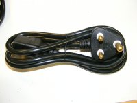

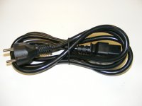
Completely OT I have some leftover power cords. The question I have is which countries AC plugs are they?
From left to right, it looks like
an old UK 15amp one, no built-in fuse. Maybe an ex-colony still uses them?
Australia, if the power prongs are angled to each other - it is difficult to see.
European. Widely used.
Cliff
That was fast so thanks to both of you. South Africa, Australia, Europe, Great. I did know the UK ones I have. I have just under 20 of each so if anyone needs some 20 amp IEC cords let me know.
The left one is Israel high power (like for air conditioners), still in use. The middle one is Australia. The right one is European.
- Status
- Not open for further replies.
- Home
- Member Areas
- The Lounge
- John Curl's Blowtorch preamplifier part II