Actually the ultimate on this subject should be Kendall Castor-Perry's articles.
Part I is here:
https://linearaudio.nl/sites/linearaudio.net/files/bypass_capacitors_part1.pdf
... but there are 5 more parts. Once read, all is clear 😉
Jan
Part I is here:
https://linearaudio.nl/sites/linearaudio.net/files/bypass_capacitors_part1.pdf
... but there are 5 more parts. Once read, all is clear 😉
Jan
Because of the bumps at 18 & 36K.
Which have been clearly indicated and spoken of in the post where you put it up, right??
Next time, how bout actually providing content? I know, I know..."that's just what they'd expect me to do..""
John
Things seem to be getting confused.
In my musings on power supplies there are many issues:
AC plug, cord construction, inlet, fuse, fuse holder, across the line filtering, power switch, transformer, transformer snubbing, rectifiers, rectifier snubbing, emi cancelation, wide band filtering, storage capacity, regulation etc.
I have tried to look at all the issues I could identify and measure both in isolation and how they interact. So the last bit on fuses was reduced to the manufacturer's data sheets give very useful information. Specifically cold resistance, resistance at rated current and thermal capacity (i^2 x R.)
Now I spoke to JC and put up a bit of old data for him.
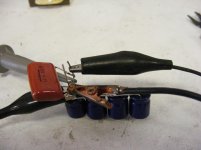
Quite nicely this brought in contributions from many others. Unfortunately as only a bit of data was presented this led to a spread of input. So to clear things up attached is a picture of the final test setup and a bit more of my musings.
The datasheets for the capacitors are here:
http://www.mouser.com/ds/2/315/ABA0000CE12-465472.pdf
http://www.mouser.com/ds/2/293/e-qxk-875906.pdf
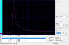
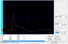
The second image is of the probes across a single 22/50 electrolytic capacitor fed from a 60 Hz square wave through a 10nF capacitor.
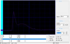
The third image is of the same capacitor but now bypassed by a 1/250 film capacitor.
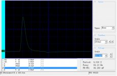
The fourth is four of the 220/50 capacitors in parallel.
The final is the bank of four with the 1/250 bypass added.
All of the resonances are extremely affected by lead length and layout that should be to no one's surprise.
I think the point is that you must measure the actual circuit to figure out the proper bypass scheme. It is way too dependent on actual layout and components. If you want to try and model this you need more than the data sheets!
In my musings on power supplies there are many issues:
AC plug, cord construction, inlet, fuse, fuse holder, across the line filtering, power switch, transformer, transformer snubbing, rectifiers, rectifier snubbing, emi cancelation, wide band filtering, storage capacity, regulation etc.
I have tried to look at all the issues I could identify and measure both in isolation and how they interact. So the last bit on fuses was reduced to the manufacturer's data sheets give very useful information. Specifically cold resistance, resistance at rated current and thermal capacity (i^2 x R.)
Now I spoke to JC and put up a bit of old data for him.
Quite nicely this brought in contributions from many others. Unfortunately as only a bit of data was presented this led to a spread of input. So to clear things up attached is a picture of the final test setup and a bit more of my musings.
The datasheets for the capacitors are here:
http://www.mouser.com/ds/2/315/ABA0000CE12-465472.pdf
http://www.mouser.com/ds/2/293/e-qxk-875906.pdf
The second image is of the probes across a single 22/50 electrolytic capacitor fed from a 60 Hz square wave through a 10nF capacitor.
The third image is of the same capacitor but now bypassed by a 1/250 film capacitor.
The fourth is four of the 220/50 capacitors in parallel.
The final is the bank of four with the 1/250 bypass added.
All of the resonances are extremely affected by lead length and layout that should be to no one's surprise.
I think the point is that you must measure the actual circuit to figure out the proper bypass scheme. It is way too dependent on actual layout and components. If you want to try and model this you need more than the data sheets!
Attachments
And how does all this change the way people hear 2 untalented in the stadium again.
Y'all ready for this?
Y'all ready for this?
And how does all this change the way people hear 2 untalented in the stadium again.
Y'all ready for this?
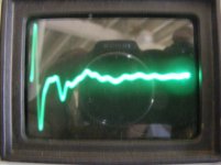
This image should confuse things even more!
It is a TDR of a 10 ohm resistor placed at the end of 50' of loudspeaker cable.
Attachments
This image should confuse things even more!
It is a TDR of a 10 ohm resistor placed at the end of 50' of loudspeaker cable.
The image is by no means confusing.
But again, I see no timebase at all, and no mention whatsoever of what it is.
50 feet of ""loudspeaker cable" doesn't help at all Ed. What is it's inductance per foot, capacitance per foot??
With no info, I can only surmise the EDC at roughly 4 and the line Z at roughly 120 ohms...reflection coefficients at each end based on a guess at line z, 10 ohms, and meter output z..
Prop velocity is roughly half C (1/sqr(EDC))
2nSec per foot, 100 n sec per length, 200 nSec between stimulus and the negative reflected return.. waveform is a bog standard expectation of driving a line not matched to the source nor load...
So you see the problem Ed? You give absolutely NO relevant information, leaving all to guess as to what you were doing (or trying to do)..or walk away from the discussion in disgust..
If you really want to show something, use a step function. I'll interpret the results of that for you..
John
JN
Gotcha. Chill. You did guess most of it right. The cable is sold as a stadium type loudspeaker cable.
But as mentioned before I am looking at how real cables behave on my size projects. I am awaiting delivery of the cable that I had made of 12 gauge twisted pairs with .011 of polypropylene insulation.
I do use a 50 ohm to 8 ohm balun for the tests.
You give absolutely NO relevant information, leaving all to guess as to what you were doing (or trying to do)..or walk away from the discussion in disgust..
Yes, you got the shtick.
AC plug, cord construction, inlet, fuse, fuse holder, across the line filtering, power switch, transformer, transformer snubbing, rectifiers, rectifier snubbing, emi cancelation, wide band filtering, storage capacity, regulation etc.
Why arbitrarily start at the AC plug (and -- what type?). What about the wiring before that, the main fuses.... the substation transformer?
What Ed has been doing is showing how we can get it wrong when making something like a power supply.
JN, please try to prove Ed wrong in some way, rather than imply it, only. You have done this to me over the last decade, and it gets tiring.
JN, please try to prove Ed wrong in some way, rather than imply it, only. You have done this to me over the last decade, and it gets tiring.
Why arbitrarily start at the AC plug (and -- what type?). What about the wiring before that, the main fuses.... the substation transformer?
Already shown the AC distribution in this thread. The power supply is something I have control over.
What Ed has been doing is showing how we can get it wrong when making something like a power supply.
What he has been doing is posting arbitrary pictures of arbitrary entities with absolutely NO relevant details. The current example of a "cable" scope shot is exactly what I'm speaking about. Just look at his response..."you guessed most of it right".
It's not about guessing!! Technical discussions require technical details!
JN, please try to prove Ed wrong in some way, rather than imply it, only.
Proving someone wrong first requires they bring FACTS to the table. What do you think I'm trying to get him to provide????
You have done this to me over the last decade, and it gets tiring.
Over the last decade, I have asked you for FACTS to support your outlandish and unsupported pronouncements. And so far, you have not provided any.
edit: In point of fact, recently I provided YOU factual content in support of your assertion that silver on silver relay contacts sounded the best. YOU did not support that statement with anything other than "I trust my ears", but I provided you actual technical content...measurements within a published paper.
I will ALWAYS request facts and content when others pronounce something technical. You are no exception.
The fact that I refuse to accept "unsupported by science" pronouncements from you over the last decade burns you, and always has. That's something you have to live with, as the scientific method is the only way to go. I expect it of me, I expect it of you. I expect it of Ed..
No exceptions.
John
Last edited:
Gents,
While you relax and think about your next move, can I wiggle in a question?
I am contemplating the use of a fuse to protect the input of a high dynamic range test system. Because the fuse is in series with the input, the fuse resistance variation must remain below a certain value so as not to cause distortion.
But for the life of me I cannot find any info about how a fuse resistance varies with the current it carries (which is in normal operation far below its fusing current anyway).
Anybody has or knows a source of such info?
Jan
PS Fully agree with Jneutron last post. For the record.
One could produce a test cell and measure the voltage drop thru the fuse with variable current . A line of interesting article would follow.Gents,
While you relax and think about your next move, can I wiggle in a question?
I am contemplating the use of a fuse to protect the input of a high dynamic range test system. Because the fuse is in series with the input, the fuse resistance variation must remain below a certain value so as not to cause distortion.
But for the life of me I cannot find any info about how a fuse resistance varies with the current it carries (which is in normal operation far below its fusing current anyway).
Anybody has or knows a source of such info?
Jan
PS Fully agree with Jneutron last post. For the record.
JN,
That TDR is a bit old as you may have guessed. It does not have a time scale. You set the relative velocity and then move a tracer and it gives you a distance. Quite useful for what it was designed to do which is indicate and locate faults.
I only posted the image because I think it nicely illustrates that loudspeaker cable often does not match the intended load. It was for fun not serious study.
No actual values are shown because it is unlikely anyone has a loudspeaker with a flat impedance, or even a cable with specified parameters other than NEC classification, gauge etc.
I will not show data on my current cable design as it is still in flux. I did have a bit of bother explaining what characteristics were required to get quotes on a sample run. They were more concerned with colors than with twist! Same issues trying to get stranding right.
Now if you want to discuss this privately, as I think you are the only one here who has pulled a bit of cable and understands the hidden issues, that is fine.
ES
Gents,
While you relax and think about your next move, can I wiggle in a question?
I am contemplating the use of a fuse to protect the input of a high dynamic range test system. Because the fuse is in series with the input, the fuse resistance variation must remain below a certain value so as not to cause distortion.
But for the life of me I cannot find any info about how a fuse resistance varies with the current it carries (which is in normal operation far below its fusing current anyway).
Anybody has or knows a source of such info?
Jan
PS Fully agree with Jneutron last post. For the record.
Yes, I mentioned measuring fuses and that the data required is pretty well covered. The major manufacturers publish cold and hot numbers. If you have a 3AG 1 amp fuse from the manufacturer's data it goes from .195 ohms at 25 C to .3 ohms at failure. This gives a tempco of about 550 ppm, a power rating of .3 watts and a temperature rise of 1.5 C per mW. All ballpark figures and will vary greatly by manufacturer.
Jan, does it matter, though? What's the load impedance?
Rin is 100K so for -120dB target it should not vary more than 0.1 ohm with 50mA current swing - better much less.
Yeah maybe I should just set up a measurement, but I am basically lazy 😎
Jan
Yes, I mentioned measuring fuses and that the data required is pretty well covered. The major manufacturers publish cold and hot numbers. If you have a 3AG 1 amp fuse from the manufacturer's data it goes from .195 ohms at 25 C to .3 ohms at failure. This gives a tempco of about 550 ppm, a power rating of .3 watts and a temperature rise of 1.5 C per mW. All ballpark figures and will vary greatly by manufacturer.
That's useful Ed thanks. I have not been able to find that info.
Jan
Rin is 100K so for -120dB target it should not vary more than 0.1 ohm with 50mA current swing - better much less.
Yeah maybe I should just set up a measurement, but I am basically lazy 😎
Jan
50mA at 100K is 5KV. So a fuse will not work. But a 50mA fuse would produce .05% distortion. A 250mA fuse would meet your resistance requirement.
- Status
- Not open for further replies.
- Home
- Member Areas
- The Lounge
- John Curl's Blowtorch preamplifier part II