Were your possibly name changing ancestors named Würzner?
Close, Würzer. I have uncovered evidence that my father actually made the change even though the umlaut was already not allowed at the immigration of my grandparents.
Why not measure them? Bob Cordell did measure fuse distortion for his book.At the risk of starting some negative vibes, I have some questions to ponder.
...............................................
Second question, does a 5 x 20 mm fuse sound the same as a 3AG of the same voltage and current rating?
See page 269.
Why not measure them? Bob Cordell did measure fuse distortion for his book.
See page 269.
I have measured them. This was in reference to the earlier post about beeswax filled fuses. There are bigger differences between brands than equal ratings in different body sizes. 1/2 amp is the fuse size with the most significant change in resistance per current ratting.
Go Ed go! Give us the info on fuses, please.
For the record, I have 'retired' from barroom fighting for several years now. It just isn't worth it, and the 'police' give me an extra hard time, if I go too far. 'Can't we all just get along?' '-)
For the record, I have 'retired' from barroom fighting for several years now. It just isn't worth it, and the 'police' give me an extra hard time, if I go too far. 'Can't we all just get along?' '-)
A fast blow fuse rated at ½ amp started off with a resistance of 1.24 ohms at .025A and increased to 1.93 ohms at .5 amps. That was the worst one I measured. (Off Brand.) Turns out the data is actually in the manufacturer's data sheets.
http://www.cooperindustries.com/con...uct-datasheets/Bus_Elx_DS_2000_ABC_Series.pdf
http://www.cooperindustries.com/con...sheets-a/Bus_Ele_DS_2015_GDB_GDB-V_Series.pdf
Note they give cold resistance and voltage drop at rated current. The 20mm fuses being shorter have a bit less voltage drop! So a prize goes to whoever can find a report of fuse testing by ear that identified that.
Last edited:
A fast blow fuse rated at ½ amp started off with a resistance of 1.24 ohms at .025A and increased to 1.93 ohms at .5 amps. That was the worst one I measured. (Off Brand.) Turns out the data is actually in the manufacturer's data sheets.
http://www.cooperindustries.com/con...uct-datasheets/Bus_Elx_DS_2000_ABC_Series.pdf
http://www.cooperindustries.com/con...sheets-a/Bus_Ele_DS_2015_GDB_GDB-V_Series.pdf
Note they give cold resistance and voltage drop at rated current. The 20mm fuses being shorter have a bit less voltage drop! So a prize goes to whoever can find a report of fuse testing by ear that identified that.
Fuses? Fuses are for wimps, not Audiophiles....
We used to routinely, way back in the day, replace power fuses with offcuts from metal variable resistor shafts. Perfect fit, never blows... moves the problem upstream!
Mind you, that was when it was considered fun to plumb a load of big electrolytics into the power points on the engineering workbench to wake up the guy who was in first and flipped the isolator for the lab to on! Bang bang bang!!
Same here but we used to wrap a few turns of solder around power plugs and put them back in.
If these fuses do make a difference it suggests really poor power suppy rejection. Some of the audiophile fuses are made from precious metals and you do wonder about how reliable they will be. Make one out of Osmium. Never blow.
Sent from my LG-H811 using Tapatalk
Sent from my LG-H811 using Tapatalk
Or try to interrupt high voltage d.c.If these fuses do make a difference it suggests really poor power suppy rejection. Some of the audiophile fuses are made from precious metals and you do wonder about how reliable they will be. Make one out of Osmium. Never blow.
Sent from my LG-H811 using Tapatalk
In 1972 I was playing reeds in the backup band for a Japanese singer, on tour of about eight cities in about ten days. The band's guitar player, the still-active fine musician Craig T. Fall, with whom I've recently reconnected, plugged his Fender amp into an innocent-looking mains outlet. This was in a large hall in Chicago.
It turned out that to suppress acoustical hum from the stand lights, tubular incandescents, the outlets supplied d.c. Of course the amplifier didn't work, and in fairly short order (as people were beginning to file in and take their seats) we smelled the telltale odor of a burning power transformer. Inspection revealed that the cartridge fuse had failed shorted, with metallic vapor condensing on the inside of the glass envelope and maintaining quite enough conductivity to smoke the transformer. Ouch! At least no one shouted Fire!
No guitar parts that night!
Or try to interrupt high voltage d.c.
In 1972 I was playing reeds in the backup band for a Japanese singer, on tour of about eight cities in about ten days. The band's guitar player, the still-active fine musician Craig T. Fall, with whom I've recently reconnected, plugged his Fender amp into an innocent-looking mains outlet. This was in a large hall in Chicago.
It turned out that to suppress acoustical hum from the stand lights, tubular incandescents, the outlets supplied d.c. Of course the amplifier didn't work, and in fairly short order (as people were beginning to file in and take their seats) we smelled the telltale odor of a burning power transformer. Inspection revealed that the cartridge fuse had failed shorted, with metallic vapor condensing on the inside of the glass envelope and maintaining quite enough conductivity to smoke the transformer. Ouch! At least no one shouted Fire!
No guitar parts that night!
And the data sheets make clear the DC voltage rating is lower than the AC voltage rating! Nice to have confirmation 🙂 .
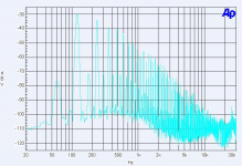
Just for fun and John here is the FFT of a simple power supply showing filter capacitor resonances.
Why are you calling full wave ripple "capacitor resonance"?
John
Last edited:
A fast blow fuse rated at ½ amp started off with a resistance of 1.24 ohms at .025A and increased to 1.93 ohms at .5 amps.
I would think AC resistance to be more important, no?
What is the resistance during AC excitation? Hook it up to the output of an amp, and sweep it into a resistive load, run the AP on it.
Now THAT would be really cool. As well, comparison of slow blow vs fast w/r to time constants.
John
Why are you calling full wave ripple "capacitor resonance"?
John
Because of the bumps at 18 & 36K.
I would think AC resistance to be more important, no?
What is the resistance during AC excitation? Hook it up to the output of an amp, and sweep it into a resistive load, run the AP on it.
Now THAT would be really cool. As well, comparison of slow blow vs fast w/r to time constants.
John
Done that. Results as expected for any resistor with high tempco.
But as Demian mentioned if your power supply can't take a joke what do you think the AC mains variations will do to it.
Because of the bumps at 18 & 36K.
Both are harmonics of 60 Hz, it's easy enough to actually plot the impedance of the capacitor vs frequency without all the potentially confounding data.
Both are harmonics of 60 Hz, it's easy enough to actually plot the impedance of the capacitor vs frequency without all the potentially confounding data.
Once the first FFT shows there is a problem. I am stealing a page from Mark J and driving the capacitor bank with a square wave through a 10nF capacitor and then trying RC networks to damp the resulting ringing.
Clearly shows that just paralleling big uns and little uns can make things worse.
It's a known phenomenon. In surge testing some poor designs get higher peaks at the output of the filters. Figuring the damping it not easy or obvious.
Sent from my LG-H811 using Tapatalk
Sent from my LG-H811 using Tapatalk
... I am stealing a page from Mark J and driving the capacitor bank with a square wave through a 10nF capacitor and then trying RC networks to damp the resulting ringing.
Please don't forget to include the part where you use linear systems theory to derive equations that tell you "if I increase X then Y should decrease" and "if I decrease J then K should get much worse" ? It was an essential piece of the work I did.
One nice feature of the application domain I chose is: hand analysis is tractable. Simulation is possible. Lab results can be confirmed two different ways. Does your study of fuses share these pleasant properties?
MarkJ
Once the first FFT shows there is a problem. I am stealing a page from Mark J and driving the capacitor bank with a square wave through a 10nF capacitor and then trying RC networks to damp the resulting ringing.
Clearly shows that just paralleling big uns and little uns can make things worse.
I used to have a spreadsheet that calculated the impedance of 4 caps in parallel, you can clearly see how it can go wrong, it might be still available somewhere, or calculate it for yourself.
- Status
- Not open for further replies.
- Home
- Member Areas
- The Lounge
- John Curl's Blowtorch preamplifier part II