Gee, I read Popular Electronics way back and learned there how to use positive feedback without oscillating. Heady stuff then. Not seeing as many designs from folks who learned their chops from PE these days.
How's the 20pV/rtHz amp going?
How's the 20pV/rtHz amp going?
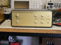
Peachy keen and dandio. Works nicely. Picture attached.
Attachments
1% is the new standard, just like 5% was standard 50 years ago.
Quite right, we use 1% as generics, 0.1% where needed -- they are only a little more expensive in volume production, unless you pick obscure values...
Try Radio-Electronics. It came into the house in the days of my youth. I think it was where I saw a project description of an RF plasma torch, which I really wanted to build. My father forbade it, wisely, as I almost certainly would have electrocuted myself with the 5kV plate supply. He himself had been knocked off a stool and rendered unconscious when working with ham radio equipment.Gee, I read Popular Electronics way back and learned there how to use positive feedback without oscillating. Heady stuff then. Not seeing as many designs from folks who learned their chops from PE these days.
Oddly he wasn't concerned about my experiments with luminous signage transformers, even though they are quite adequate to induce atrial fibrillation. I think his theory was that being a.c. one wouldn't hold on to the source. Although it is true that d.c. is more effective in inducing muscular contraction, the a.c. is still sufficiently paralytic.
Peachy keen and dandio. Works nicely. Picture attached.
Some results to share?
Try Radio-Electronics. It came into the house in the days of my youth. I think it was where I saw a project description of an RF plasma torch, which I really wanted to build. My father forbade it, wisely, as I almost certainly would have electrocuted myself with the 5kV plate supply. He himself had been knocked off a stool and rendered unconscious when working with ham radio equipment.
Oddly he wasn't concerned about my experiments with luminous signage transformers, even though they are quite adequate to induce atrial fibrillation. I think his theory was that being a.c. one wouldn't hold on to the source. Although it is true that d.c. is more effective in inducing muscular contraction, the a.c. is still sufficiently paralytic.
Here is was The Radio Constructor, and Practical Wireless... Got me building my first radio kit aged 9! One of my teachers was horrified when she saw me testing a 9V battery with my tongue, told my folks I was nearly electrocuted!
Try Radio-Electronics. It came into the house in the days of my youth. I think it was where I saw a project description of an RF plasma torch, which I really wanted to build. My father forbade it, wisely, as I almost certainly would have electrocuted myself with the 5kV plate supply. He himself had been knocked off a stool and rendered unconscious when working with ham radio equipment.
Oddly he wasn't concerned about my experiments with luminous signage transformers, even though they are quite adequate to induce atrial fibrillation. I think his theory was that being a.c. one wouldn't hold on to the source. Although it is true that d.c. is more effective in inducing muscular contraction, the a.c. is still sufficiently paralytic.
Of course I got both. But Gernsback (SP?) made Radio-Electronics a more technical style publication. P.E. was a bit of a looser cannon with more reader projects some of imaginative but possibly Iffy design and construction. The example that keeps popping up here is the Tiger amplifier where the biasing as designed and sold was a bit of a problem. But I think they were the first with the CFP output stage.
You might want to rethink why some projects that could burn down the house were a bad idea but the ones that would only injure you.... 🙂
Waly,
Already shown without the transformer and if you look at the picture you can see just one of the step up transformers.
Last edited:
Electronics Illustrated. It had Uncle Tom Kneitel, which was worth the price of admission.
Some of us old timers built regen receivers.
Some of us old timers built regen receivers.
Yup, single tube regen. I always thought that was so cool - the signal going through the valve twice - RF then AF.
I built mine on the kitchen table with my dad's plumber's soldering iron on the gas ring. My mum was not impressed!
I built mine on the kitchen table with my dad's plumber's soldering iron on the gas ring. My mum was not impressed!
No mouth parts intended at all. 5-15ppm topping out at a quarter watt. Not sure where the high power application is relevant.Very nice for the feedback resistor in a big amp - especially CFA where you need low(er) values that result in higher Pd (can be 2-3 watts in a big CFA if you want to preserve SR and bandwidth)
However, I guess your comment was more tongue in cheek 😀
Certainly for small signal duty thin film 1206 SMD devices are an excellent choice.
http://www.mouser.com/ds/2/427/ptf-239718.pdf
Suppose an amplifier or preamp has 1nV/sq rt Hz voltage noise density input devices, and for whatever reason one wishes to have that noise dominate. Suppose it's a power amp and one designed to produce 400W into 4, and have a voltage gain of 26dB. Suppose we set the feedback divider resistor value to be a thermal noise contribution well below the input differential pair noise (for the sake of argument a VFA and a differential pair at the input). Let the feedback divider contribute at a level of 1/3 of 1.4nV/sq rt Hz. Then it will be about 13 ohms. For the desired gain the feedback R will be 19 times this, or about 250 ohms. For full power out the output voltage will be 40V rms. The total feedback resistor and feedback divider resistor dissipation will be about 6W.
Why then do you drive 20 year old Acura and complain about DAC's you can't afford?
Have you seen the women John keeps at his side?😉
Well, to be fully accurate, 1206 thin film resistors are not exactly 10 cents a pop, but more like at least x10 that.
What's the 1000's price break? In this context that's all that matters.
Peachy keen and dandio. Works nicely. Picture attached.
Those connectors won't support thermal emf's at that level all the time. I picked up 2000 AD797's in cerdip last week they're free to me (I know it's not fair) time to set the kids up with soldering irons. Or do I need 3000 or maybe 4000, let's see.
Attachments
Last edited:
Some results to share?
The process will be painful to be sure.
Those connectors won't support thermal emf's at that level all the time. I picked up 2000 AD797's in cerdip last week they're free to me (I know it's not fair) time to set the kids up with soldering irons. Or do I need 3000 or maybe 4000, let's see.
🙂🙂🙂🙂
I have given up at 20. Boring enough.
And the problem is the bias current that requires a small bias resistor
that requires a huge input cap, wet slug tantalum if possible :-(
Since the bias seems to be predictable, one might provide most
of it with a current source???
Currently I'm trying 4 IF3601 ( really 2 IF3602).
OMG. IDss varies all over the place. 1 : 20.
Even the partners in a pair are quite different.
If I was in IF's shoes I also would avoid writing a data sheet.
Unfortunately they are not free, up to now I have spent €500
for just 10 pairs...
BTW your optical bias generator works like a charm. It doesn't
matter if I use 1, 2, 3, or 4 of these FETs; Id stands to 3 decimals.
wow!
I had to decrease the cap over the generator side, there was
motor boating otherwise.
regards, Gerhard
Last edited:
🙂🙂🙂🙂
I have given up at 20. Boring enough.
Currently I'm trying 4 IF3601 ( really 2 IF3602).
OMG. IDss varies all over the place. 1 : 20.
Even the pairs are quite different.
If I was in IF's shoes I also would avoid writing a data sheet.
Unfortunately they are not free, up to now I have spent €500
for just 10 pairs...
BTW your optical bias generator works like a charm. It doesn't
matter if I use 1, 2, 3, or 4 of these FETs; Id stands to 3 decimals.
wow!
I had to decrease the cap over the generator side, there was
motor boating otherwise.
regards, Gerhard
Good to here it, always like to help. Almost embarrassing this week I was cause celeb over the LIGO results, BTW it was the German team that built the actual instrumentation packages for the "bake off" to upgrade LIGO. They still don't know why ours came out ahead.
They still don't know why ours came out ahead.
Do you know why?
-RNM
:
Currently I'm trying 4 IF3601 ( really 2 IF3602).
OMG. IDss varies all over the place. 1 : 20.
Even the partners in a pair are quite different.
If I was in IF's shoes I also would avoid writing a data sheet.
I believe those were designed for thermal/IR imaging in spacecraft and not intended to be used as diff pairs originally. Also they sort by looking at adjacent pairs on the die which should help but their process and equipment is not particularly new. When I was buying from them (years ago) it was 2" wafers and I just bought a complete wafer and had them paired and mounted in cans. Old school anyone?
Where do we get to see the optical bias generator? it might even have credibility with fashion audio if its unusual. I remember some nutcase was popping the tops off of power transistors and controlling them with light, using a bunch of magical claims for it.BTW your optical bias generator works like a charm. It doesn't matter if I use 1, 2, 3, or 4 of these FETs; Id stands to 3 decimals.
wow!
- Status
- Not open for further replies.
- Home
- Member Areas
- The Lounge
- John Curl's Blowtorch preamplifier part II