Pavel and Soundmind, now we are on track. I am glad that you both knew this, but I had to make sure that everyone reading this did not get confused in the discussion we were having. By the way, Pavel, I have a degree in Physics-Engineering for the very same purpose of understanding such models. My weakness in education was atomic physics, not differential equation based models.
The reality is that MM cartridges have more or less damped resonance at the high end of their frequency response. Electrical amplitude overshoot sometimes tends to equalize a loss of high frequencies, that's correct. BUT, the frequency response is never flat. It always has a tolerance within 1dB or more.
As we say where I come from, for a cartridge, +/- 1db is good enough for government work.
There is no reason to prove one's knowledge.
I'm not in the audio business, for me it's just a hobby. And not one I'm particularly passionate about. At least not about phono equipment.
Any record with as low as 0.01% harmonic distortion in a vinyl groove is physically impossible. Order of 0.1% - 1% would be true, depending on rpm (45 is better than 33), amplitude, frequency and diameter - distortion is getting higher near the center of the disk. Theoretical values of distortion are known and cannot be outperformed.
I agree with PMA .01% is physically impossible at 5kHz and resonable levels, let alone gettikng the noise floor down to <-80dB so you could even see it. The mistracking is computable.
MC cartridges also have a frequency response deviation from scanning losses from the stylus/groove interface. This depends on what radius you play the record, so it can ONLY be approximated, at best.
EMT did a good job, 40 years ago, by having a lower resonance (30KHz) with a moderate Q. This filled the 'saddle' nicely. Shure does it by adjusting the elements of its 4 pole filter to be a 1/2 to 1 dB Chebyshev low pass filter, putting the mild boost at the right place to cover the scanning losses.
Most MC cartridges have a slight shallowness in the upper midrange, especially if they are VERY wide band and well damped. This is normal. Modern stylii have reduced scanning losses
Still other MC cartridges are very UNDAMPED and they DO RING strongly at their own resonant frequency, and this mixes with the SQ Wave test record's 'resonant frequency' and you get a difficult to unravel, result. Most oscillograph pictures of SQ waves of phono cartridges are very confusing, if you don't know about all the interactions.
All class A systems reduce their distortion monotonically with level. Therefore, low level gives low distortion. Who cares about .01%, anyway? Do you think that you could hear added .01% second or third harmonic added to your system?
Last edited:
The ringing is on the TEST RECORD ITSELF. Wake up and smell the coffee!
If the cutter rings producing test records, then why wouldn't it ring producing all other records as well? I presume it's the Westrex 45/45 cutter. And how would it explain all of those cartridges whose outputs didn't show any signs of ringing in their photographs with a 10 khz excitation? Not likely they would all have a trough at exactly the same frequency and amplitude as the cutter rings at. Not all of them.
How many plays is the test record good for? One play would be my guess. After a single play, it would be suspect of having been distorted by deformation during prior playings....with cartridges that rang.
Starting no later than the mid 1960s, Scanning Electron Microscopes could take photos of record grooves. I think Shure actually used such a photo made at 25,000 magnifications in one of its ads. If a square wave cut into a record had ringing to it, you should be able to see it in such a photo. The side walls of the groove would show the added indentations.
Quote without comment: HPR Vol.1,#1 p.28 "... Clear presentation of the cutter head ringing that is on the CBS STR 112 test recording indicates extended response to about 50KHz. The rise time of the cartridge as measured with an expanded view of the leading edge of the square wave was under 10uS." Clear enough?
All class A systems reduce their distortion monotonically with level. Therefore, low level gives low distortion. Who cares about .01%, anyway? Do you think that you could hear added .01% second or third harmonic added to your system?
You should pay attention to what we were discussing. At low enough levels the tracking distortion vanishes for many cartridges, we were addressing the claim that at some level there was a 1.5-.01% range. Maybe at 100Hz, who knows, but not at 5kHz. Or maybe there is another distortion mechanism.
No scopes needed just play 1/3 octave 5kHz noise.

I personally do not see this as real or important.
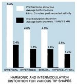
What I would do would be to map the 2'nd and 3'rd harmonic distortion with frequency from a sweeping test record at some standard level. This could have been done in our lab in Switzerland with a tracking wave analyzer. Today, we might use an fft based analyzer. Then, after trying several sweep test records from the USA, Japan, and Denmark, I would take the lowest overall distortion reading at any specific frequency range, and then predict the distortion for lower amplitude levels with what we know mathematically about distortion generation in a class A system.
Perhaps, you are talking about a scanning problem with a finite cartridge stylus, knowing that a more narrow connecting 'patch' will ultimately destroy the record, if you are not very careful. Kind of exotic, isn't it?
Last edited:
I would also like to point out that looking at the record itself, you will NOT see square waves. You will see TRIANGLE WAVES. The output of the cartridge is the DIFFERENTIATED output, tracked by the stylus. Therefore the superimposed sine wave from the cutter resonance will be suppressed by approximately 30 times, with the STR 112 test record. Under normal cutting conditions, the slight bump in the frequency extreme, at or above 20 KHz will be incorporated into the record pre-emphasis to get a better frequency response to 20 KHz, or even above, with more modern disc cutters by Neuman or Ortofon.
Many here might also come to understand why many experienced audio designers find most distortion below .01%, with 2'nd, 3'rd, or 4th harmonic distortion or its related IM products to be rather forgettable. However, HIGHER ORDER, especially 7th harmonic distortion, is very bad, and perhaps 100 times more important than 3'rd, at the same level. This has been well known for the last 80 years, at least.
A direct response from the mix engineer, Dan Healey, for the Grateful Dead for about 25 years, today, gave me: Avg un-weighted level, 103 dB Coverage very general, even on stage. 110dB or more peaks possible. Most acoustic energy below 200 Hz.
The zip mutates into a "CLP" i can not open.
Try the press paper..
it s a piece of a pdf format.
edit ; right, it doesn t work....
i ll find another way..
Here we are, the complete pdf...
http://www.shure.com/idc/groups/tech_pubs/@global_managed/documents/webcontent/us_pro_v15iv_ug.pdf
Last edited:
Relevant bit for those who don't want to download 1MB....Here we are, the complete pdf...
http://www.shure.com/idc/groups/tech_pubs/@global_managed/documents/webcontent/us_pro_v15iv_ug.pdf
Attachments
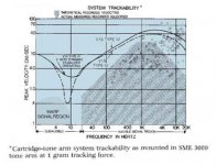
Their measurements of peak recorded velocity are interesting too.
Looks like a MM preamp can expect to see close to 100mV peak input in the treble, even without clicks and pops.The shaded area at right represents recommended theoretical limits of record cutting velocities. The scattered points are the "hottest" recorded velocities actually measured on difficult-to-track records.
Attachments
First, take into account cartridge load resistor (and parasitic capacitances). The 47k is not any cure.
A complete model if such a thing even exists must take into account at the very least;
The mechanical system including the modulus of elasticity and linearity of the stylus suspension, the modulus of elasticity of the vinyl whose composition varies from manufacturer to manufacturer, the effective inertial mass of the tonearm and its moment of inertia with respect ot the pivot point (for a pivoted arm) depending on its distance from the pivot point, bearing and tone arm wiring friction, the force exerted by the stylus to overcome the moment of inertia. (You can see the effort to reduce stress on the vinyl by increasing contact area to achieve the required force by use of high contact area stylus geometries), and overall alignment geometry. (pivoted arms inevitably create time errors since the inner wall is being tracked at one point in time compared to the outer wall with respect to the way the groove was cut by the radial tracking arm.) Newton's second law as applied to forced oscillation is helpful in this regard to this part of the analysis.
The mechanical to electrical conversion efficiency of the cartridge as an electrical transducer. This includes the magnetic circuit taking into consideration coil efficiency and alignment, core losses due to eddy currents and hystersis loss, mutual transconductance of the coils and magnets, linearity of distribution and density of the magnetic flux in the region of the coils, alignment of the magetic system, and the overall electrial properties of the entire assembly.
That gets you to the Thevenins equivalent of the source which must then be used with the equivalent lumped sum parameters for the tone arm wiring/interconnect wiring for the network analysis to calculate the transfer function to the complex impedence of the phono gain input stage.
The equivalent cicuit of the phono gain circuit including any feedback if there is any. The accurate calculation of the feedback circuit is in my experience one of the most difficult parts considering how many equations there are in it. (Small wonder most designers get it wrong and create more problems than they solve, then dismiss negative feedback as worthless and counterproductive.)
And then there is the coupling of the output circuit to the next gain stage incorporating the Thevenin's equivalent of the output, the equivalent lumped sum parameters of the wires, and the complex input impedence of the following gain stage.
Output voltage is usually specified at 3.54 cm/second but as can be seen from the graph for Shure V15 Type IV, output can be ten to thirty times that high. (Hopefully the power supply to the phono stage can handle that into the next stage input load without being loaded down itself.) Typical outputs for MM carts at 3.54 cm/second range from about 2mv to 10 mv while MC cartridges are about one tenth that except for high output types.
It would not surprise me if the results of most calculations are orders of magnitude in error due to oversimplification and the wrong parameters, even the wrong equations. A figure of 4% to 8% combined THD + IM + noise for the best cartridges is not the least bit surprising to me. And this is just for the phono cartridge, this doesn't include the microphones and loudspeakers. (Dr. Bose said the threshold of hearing non linear distortion is about 6%. ) And while linear distortion can be compensated for in the playback system, once non-linear distortion arises at one stage, there is nothing you can do to remove it in a later stage, you are pretty much stuck with it. The attempt to build a one size fits all phono stage given the number of variables seems like an effort in futility. But then some people enjoy banging their head against a brick wall I suppose.
By comparison, the equivalent for even cheap Redbook CDs is a small fraction of one percent. This is one reason why I consider vinyl phonograph records to be donkey cart technology. However, people do pay money to ride in a horse drawn carriage through Central Park on a nice sunny day.
- Status
- Not open for further replies.
- Home
- Member Areas
- The Lounge
- John Curl's Blowtorch preamplifier part II