Thank you Demian
http://www.ko4bb.com/Manuals/Tektronix/Tektronix_-_Probes/Tek_P6021_Current_Probe.pdf
http://exodus.poly.edu/~kurt/manuals/manuals/Tektronix/TEK%20P6021%20Instruction.pdf
http://www.hpl.hp.com/hpjournal/pdfs/IssuePDFs/1960-07.pdf
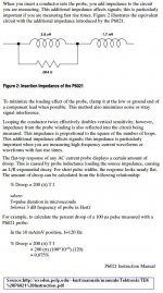
I have a relevant dump question. When we double the number of loops around the current probe, would all the L and R of the reflected impedance raise to the square of the value shown in Fig.2 ?
George
Attachments
P6042
Google P6042 for manual;
I have a P6021 probe but the limited low freq response is sometimes a problem. The P6042 is flat down to DC. It combines the transformer pick-up coil with a Hall Effect device to provide 1 mA to 1A/div from DC to 50MHz. I like it a lot... for measuring DC current flow in circuitry, as well, as HF.
THx-RNMarsh
Last edited:
You know, the problem is that we can argue, parse, and quibble over something like measuring the differences between slow and fast diodes, and not really get anywhere as this question was answered over 20 years ago, and implemented in most hi end audio equipment today.
The input inductor is to keep out rf and keep the input from oscillating.
Perhaps a damping resistor (to gnd) on the opamp side of the coil? I'd be a bit concerned about getting a resonance between the input C of the AD797 and the inductor as the input's high impedance.
Remarkably, 😛, a pretty good technique for getting optimum sound from kit is to work backwards - know exactly what you're after, and keep whittling away at the bits until you get the desired result. Diodes may or may not be part of the answer, but unless you can assess whether using a particular species is giving one a worthwhile gain then, in one sense, it's working blind.
Something like getting a flat surface 'truly' flat, to a certain precision - there are always a few bumps left after each stage of scraping the high spots; are the remaining bumps still too high, or is another round of levelling required? The big question then is, what is "too high" ... 😉 ?
Something like getting a flat surface 'truly' flat, to a certain precision - there are always a few bumps left after each stage of scraping the high spots; are the remaining bumps still too high, or is another round of levelling required? The big question then is, what is "too high" ... 😉 ?
You know, the problem is that we can argue, parse, and quibble over something like measuring the differences between slow and fast diodes, and not really get anywhere as this question was answered over 20 years ago, and implemented in most hi end audio equipment today.
OK. Now what are a few of the solutions to this PS diode noise generator? The DIY'er isnt always aware of what the industry did/does nor when and why.
One of the more popular apps to this issue is to put small value C across each diode. Is it totally effective?
THx-RNMarsh
Last edited:
George
Thanks for sharing these, I've owned a 6021 with a type 134 amplifier for years and never had the manual to refer to. Ain't the internet great!
Mike
OK. Now what are a few of the solutions to this PS diode noise generator? The DIY'er isnt always aware of what the industry did/does nor when and why.
One of the more popular apps to this issue is to put small value C across each diode. Is it totally effective?
THx-RNMarsh
The bypass is not as effective as the faster switching diodes. The small bypasses on each diode let in more line noise.
I need to repeat the measurements at higher load currents. As can be expected the transformer inductance comes into play.
As a general design a single capacitor across the secondary and low noise diodes work best. Also use two bridges not a center tap as the center tap always let's in noise.
See "Rectifier Snubbing- Background and Best Practices" by Morgan Jones in Linear Audio Volume 5 for a good analysis and the right way to accomplish this.
Ain't the internet great!
It is a powerful tool, accessible to many .
🙂
George
The small bypasses on each diode let in more line noise
Aha - just as I always suspected !
Been playing in spice to optimize my power supply design and came up with this.
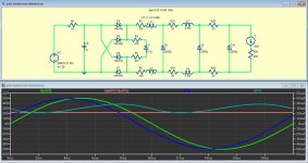
It wouldn't win any prizes for efficiency - the supply dissipates twice as much as the load ! but I think I can deal with wasting 1W. What I like is the close correlation between current & voltage in the secondary and the clean 100hz ripple in the chokes.
V(n002) - green, is voltage o/p of transformer secondary.
V(n007)-V(n015) - pink, is the output voltage.
The currents are self explanatory. The little glitch in the inductor current at 10ms can be entirely removed by trimming the values of R3 & R4.
Any suggestions welcome - will start building soon and will use schottky diodes as always.
mike
Attachments
I would split R6 into both transformer leads.
Keep in mind that inductors have lots of problems. Values can swing with current, they may also be affected by mounting (near each other or a bit of metal) and they can radiate fields.
I look at interference noise from three angles. First is the AC line noise, it comes in common mode or differential flavored. It looks like you can handle differential from this schematic. Common mode is improved by not just no transformer connection to electrical common, but also by transformer choice, layout and some version of line filters.
Then there is magnetic flux leakage. A tightly coupled transformer helps as does shielded inductors. Some go as far a putting torroid transformers inside tubular cases. These are the kinds of things not shown on circuit theory schematics.
The third class is EMI or radiated energy. This may come from anything such as radio stations, fluorescent lights, small motors or even be generated inside the power supply.
Vacum tubes and FETs handle EMI better than bipolar junction transistors. So this is one of those issues where changing an IC in a device can lead to a sonic improvement when the specifications would indicate that should not be the case. (FET input replacing BJT )
Last edited:
Thx Ed,
In reality R6 is the secondary resistance so it is evenly split.
I tend to decouple the ground to deal with common mode noise.
I like lots of space around my circuits and chokes to avoid the potential problems you allude to but in this project my space is limited so I will do the best I can but I do have separate steel boxes for the supply and the actual preamp so that will help.
The production line I worked with had a break in process, I believe it was either 200 volt or 400 volt. The issue as I recall was vf.The 1N4007 is supposed to be/was a little different from the others. The note in the link mentions the long recovery time of the 1N4007 specifically. I don't know if a process can yield from 100 PIV to 1000 PIV without a lot of tweaking and sorting to get the different voltages is not practical for large volume production.
Thanks, I'll look at that when I get a chance. Turn ON time??, TFR..measured that as well back in the 80's, but nobody seemed to worry about that, it was always TRR that gave problems.
Without proper measurement, your just chasing your tail. For example, ed made the assumption that the faster diode had no transient on the first probe setup, but it can also be that it didn't make it through the probe. Before making proclamations as to diode turn on characteristics and application to any circuits, it's important to actually know what the characteristics are.You know, the problem is that we can argue, parse, and quibble over something like measuring the differences between slow and fast diodes, and not really get anywhere as this question was answered over 20 years ago, and implemented in most hi end audio equipment today.
That is not a good assumption. Some diodes snap at the tail end of their turn off, and radiate rf like crazy. It's far more worthwhile to know what is actually happening.Better yet, just use faster diodes.
The bypass is not as effective as the faster switching diodes. The small bypasses on each diode let in more line noise.
Don't forget, a diode in forward conduction also has a very high junction capacitance. In reverse, it can drop into the picofarads, but in forward it can be microfarads.
I would split R6 into both transformer leads.
Keep in mind that inductors have lots of problems. Values can swing with current, they may also be affected by mounting (near each other or a bit of metal) and they can radiate fields.
Certainly concur with mounting, especially if copper or aluminum is nearby, nevermind steel.
jn
JN,
A picture is worth a thousand words except here, no one seems to look at the pictures.
Next up a discussion of why you have to use a 10X scope probe and not a 1X if anyone is interested.
A picture is worth a thousand words except here, no one seems to look at the pictures.
Next up a discussion of why you have to use a 10X scope probe and not a 1X if anyone is interested.
JN,
A picture is worth a thousand words except here, no one seems to look at the pictures.
Pretty much par for the course.
Next up a discussion of why you have to use a 10X scope probe and not a 1X if anyone is interested.
For this fast stuff, I always use those little probe tip adapters. If I want to pick up extraneous noise or limit risetime, I'll use the flying ground lead.
A foot of coax does "wonders" to half nanosecond risetimes...
jn
As to the article it talks about electron flow when it should be charge. Scott will get confused again. The careful reader will not the issue occurs at lower levels even inside conductors that have metallurgical impurities or even micro cracking. So all it does is open last months can of worms.
The first of your twenty questions last month was based on a so totally flawed concept of conduction that at first neither I nor jn could even figure out what it was. Please have your references handy next time.
Possibly you could explain the meaning of "electron flow when it should be charge", the thought is incomplete.
To clarify the matter of diode selection:
We found that typical power diodes, like the 1N4007, were non-optimal for 60Hz power supply rectification (among other applications) when used in audio equipment.
This is NOT an intuitive concept, and almost nobody thought about it for decades after solid state diodes began to replace vacuum tube rectifiers. I even tried to replace the GZ34 in Dyna power amps with 1N4007's, and I was disappointed in the sound difference. Yet, WHY?
Well, this is where diode turnoff comes in.
The standard devices work well enough to rectify efficiently, but they leave a 'tail' of RF residue due to their slowness in turning off. That is the essence of what Ed Simon actually demonstrated with his photos.
It is the COMPARISON between the slow (1N4007) and faster diodes that was really important, not whether his probe was 'perfect'. JN concentrated on the 'measurement accuracy' rather than the comparative results.
Now JN is correct in that there is a little more to it, for example, some really high speed diodes (made for a completely different application) might NOT be a suitable substitute, but serious hi end designer already know this, and we use 'soft recovery' types, exclusively. It is not hard to copy what the successful designers use, as they are usually offered at specialist audio parts websites.
So, the point is to use 'optimal' diodes for your high end audio supply.
- Status
- Not open for further replies.
- Home
- Member Areas
- The Lounge
- John Curl's Blowtorch preamplifier part II