The current in a speaker is not building up insteaneous. So it is well known that a good power amplifier can not only provide voltage but a lot of pulse current too. That is especially important nowadays where modern loudspeakers are wideband and linear but do not have high sensitivity because people want small speakers that produce a lot of bass
, sacrificing sensitivity in the process.
How much current do we need ? I tested a lot of even very big woofers, say a JBL 18 " woofer with a 100mm voicecoil. Non of the woofers could stand more then 11A over a sustained period, simply burning the voicecoil. That does not mean that we not need more current over a short period of time to excellerate the driver. I would say that 45A over a 500msec period is fine, even for big Wilsons, Rhaidos and Magicos that set the pace at this moment in time. I do not build current hungry speakers like that but this is not the place to advertise. Problem with say a 300W amp with 45A peak delivery is that the low revel resolution of an amp like that may not be as good as a class A amp with 25W although many of the high power amp makers will not agree. Do not trust me but it is hard to find a huge power amp that sounds " Real".
Concerning an FFT on an only positive going signal ( e.g "noise" ), where is the problem ?
Are you all stupid discussing this in public ? I thought you are the experts.
Even Fourier allowed Sine, Cosine and Half Cosine ( only positive going ).
Here is a text ( sorry in german, i break the rule ) :http://www.kirchner-elektronik.de/~kirchner/photostoryteil2.pdf
Joachnim, I respectfully suggest that you come from a different design philosophy and culture than most people here.
Consider the old DIN 45500 standards. They stipulated that a speaker shall have an impedance of nominally 4 Ohms. Now look back at German products (while they were still REALLY German products, not rebadged Japanese products). See how many you find which did not allow for the possibility of driving two pairs of speakers at once, which would make the load NOMINALLY 2 Ohms.
My point is, Germans are used to dealing with low impedances, they always have, to them it's old hat. As opposed to the Japanese industry, which was centered on 8 Ohms and usually had problems every time that dropped to 6 Ohms or, God save us, below that.
As a result of that, Japanese amps always sounded louder than most German amps, but just about every German amp had more body and texture than just about every Japanese amp (my hat off to the eceptions). Becase this was so, German amps never needed wild power spects to sound substantial, they generally did it by 2-3 Watts, which is what most of us (except Wayne) usually need for everyday listening. Your Grundig V5000 would musically shame practically any Japanese amp in its 8 Ohm power range (rated at 70/120W into 8/4 Ohms).
And the ASC V 5000 integarted amp is the only one left on my to-buy list even after all these years.
As for your maximum current requirements, let's not forget the power robbing crossover network. Can you tell how much that raises the voltage/current requirements?
Pity that it is such a poor translation. Unclear to me whether the translator didn't understand what he was translating, or wasn't a native English speaker himself.EUVL said:But there is an English version :
PRBS as a way of characterising complex systems has been used by control engineers for decades. I helped write some code to support this in the power industry about 20 years ago.
Don't forget that near the crossover region the crossover network may reduce current requirements, as it may partly balance off bass and treble reactive currents.dvv said:As for your maximum current requirements, let's not forget the power robbing crossover network. Can you tell how much that raises the voltage/current requirements?
Many modern speakers have low bass equalizer in the x-over, so they need higher currents , especially critical when the phase there is turning. Beside that we have modern passive x-overs up to 60dB steepness, this cost efficiency thus more current needed.
Yes, the translation is clumsy. I hope to find a better text about what is called " dynamic measurement ". The idea is that a signal is used that has only positive values.
In this paper it is a series of half sines. The signal sounds very unpleasant. Like " Brrrrrr." or "GGrrrrssss".
In this paper it is a series of half sines. The signal sounds very unpleasant. Like " Brrrrrr." or "GGrrrrssss".
Sorry, i can not find a better text in english.
Here are some more graphics :Dynamic Measurement- Grundlagen, Meßergebnisse und Vergleich mit anderen Messverfahre - open-end-music-professional
It seems to be that this kind of measurement is not much used outside of Germany.
Even in Germany not many designer are using it because it is kind of cruel, showing the product in a bad light so to say.
It shows that most speakers do not only reproduce the positive going sine " train " but also a negative going signal that was not present in the original information.
This fals signal comes from the fact that a dynamic loudspeaker is a mass-spring system that can not simply being stopped by the damping factor of the poweramp.
Also a non linear phase crossover stores energy in the all pass term.
Heck, I bet that I have more knowledge and experience than 90% of my critics here, when it comes to speaker design.
HAHAHAHAHAHAHA!!!!! Oh my *catches breath* thanks for the hearty laugh and comedic entertainment 😀
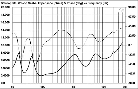
Here some work has beeing done on what load a speaker presents to the amplifier :Heavy Load: How Loudspeakers Torture Amplifiers | Stereophile.com
Balls made of glass, not brass.
Marantz PM-15S1, 1 pair of A1303/C3284 (125W TO3P) and >50V rails.
Protection allows 15A peak output current, rest is handled by a TA7317P chip.
Want Marantz with TA7317P and larger underwear, buy 6-pair A1216/C2922 monaural MA-9S2's. (sets one back $15k though)
HAHAHAHAHAHAHA!!!!! Oh my *catches breath* thanks for the hearty laugh and comedic entertainment 😀
Actually, I could see his (JC's)point. Designing an amp does require understanding the load, especially if you want to push the amp hard without breaking it. In terms of the speaker's impedance and phase, he may very well understand more than most.
Since my sworn duty is to diss JC wherever I can, I believe my words here carry more weight...
jn
Well ,
No definition as to what is a "big amplifier", is it the 8ohm power rating (what amount) or it's low-z power rating. excessively steep xovers necessary to run ceramic Pistonic drivers is a big problem.
No definition as to what is a "big amplifier", is it the 8ohm power rating (what amount) or it's low-z power rating. excessively steep xovers necessary to run ceramic Pistonic drivers is a big problem.
My biggest concern with the vacillation of the minimum impedance number by the committee has to do with the impact it has on the entire industry.
As a speaker designer, the 80% is a harder goal. Now, I have to re-design the products so that I stay above 80%. Sometimes I use lower impedance to pull more power out of the amp at frequencies where either the driver or cabinet efficiency drops, that way I remain flat across the bandwidth. The new requirement forces me to redesign, or back off on my specs, losing market competitiveness. At least it tones down the thermal requirements on my voice coils.
As an amp designer, it's about time. I'm tired of trying to protect my product against half impedance current draw. I design my amps to just meet NEC draw requirements, and those low z cabs cause my product to pop circuit breakers.
As a soundboard operator, now I can rely on the compressor to protect my system against those silly bassists and synth nuts, because my compressors are voltage devices and those LF guys always want to push the envelope (murphy's law #42 states that the best bass notes are the ones where the cabs draw the most current).
As an electrician, now I can put a one line together without worrying about some bassist or synth guy doubling the power requirement just because they like kicking bass on a note where the cabs are half impedance. At least I don't have to double the service panel size as another safety factor, it's about time those AES guys helped us here...
WHAT??? Back to 50%????
jn
Actually, I could see his (JC's)point. Designing an amp does require understanding the load, especially if you want to push the amp hard without breaking it. In terms of the speaker's impedance and phase, he may very well understand more than most.
Since my sworn duty is to diss JC wherever I can, I believe my words here carry more weight...
jn
Please, JC's experience with "speaker design" last appeared back in the 70's.
Of course speaker impedance load has to be taken into consideration and Stereophile (ugh I hate to admit that they manage to do this right in spite of themselves) publishes the impedance curve along with the phase of every speaker they test. As long as the phase and impedance doesn't doesn't get to wild, an amp can handle things nicely.
Speaker impedance becomes most capacitive around the .707 point in an impedance peak (in general) as the frequency increases. For instance in the following attachment, the Wilson Shasha has a -45 degree capacitive phase at 55Hz at 5 ohms.Also drops to 3 ohms and –43° phase angle at 61Hz Not an easy load. Also note that it dips to 2 ohms from 80 to 100 Hz. Better have a robust amp to handle that.
My amusement came from JC's claim as to speaker experience.
Last edited:
(murphy's law #42 states that the best bass notes are the ones where the cabs draw the most current).
jn
Murphy must have been a real loudspeaker designer. This typically happens (best bass) where the output of the bass pipe is max and cone excursion minimal, so that is where back emf is lowest.
That's ok. Physics is pretty much the same. I do find however, your knee jerk bashing of everything JC says to be a bit tiring. Perhaps you could find within yourself the ability to tone it down a tad? I'd appreciate it.Please, JC's experience with "speaker design" last appeared back in the 70's.
Of course speaker impedance load has to be taken into consideration and Stereophile (ugh I hate to admit that they manage to do this right in spite of themselves) publishes the impedance curve along with the phase of every speaker they test. As long as the phase and impedance doesn't doesn't get to wild, an amp can handle things nicely.
Perhaps. What does concern me is the plotting data of speakers which interact with the cabinet to achieve the impedance shown on the graphs. There is a detachment between the sine reactance and the step reactance when multiple energy storage mechanisms are at work within a cabinet. Case in point, reflex and tuned enclosures which introduce group delay, vs horns or overdamped infinite baffle. edit: In designing output protection, the step reactance is important.
I understood that. However, as you stated, ""Of course speaker impedance load has to be taken into consideration"" (with amp design). Since JC is indeed an amp designer, I would assume he does do that.My amusement came from JC's claim as to speaker experience.
As a buyer, I would expect a reasonable level of speaker load expertise on the part of the designer of any power amp equipment I would purchase..
jn
Last edited:
I am not sure what the reason is to find a single number for a speaker's variable Z. Unless, it is to appease commercial interests, primarily. I mean it is not like the 50 Ohm or 75 ohm Z standards.
After all, don't amps need to handle cleanly the speakers minimum Z at all times? I dont want to know the 50 or 80% value. Just give me the lowest Z value, thank you.
THx-RNMarsh
Dick,
I'll be glad to answer your question. 2 ohms for a JBL 8 ohm rated professional series cone transducer.
Now the background. JBL used to offer the same transducer for both pro and consumer use. It would be rated 4 ohms for the consumer and 8 for the exact same model sold to a pro. That was because pro amplifiers could handle the dip in impedance and consumer gear didn't.
Now as we are talking about transducers, it should be clear that the DC resistance of the voice coil contributes nothing to the actual output energy. So for a midrange or higher frequency driver you are misleading if you use an impedance value of 1,25 times the DC resistance as the impedance in the working frequency range is often higher than that,
There are two issues that raise the impedance, one that is well known is that there is inductance in the voice coil. The other that should be obvious but is often ignored is that the devices are transducers! That means they convert electrical energy into motion which moves the air and produces sound. As that we requires energy we see it as additional resistance. What is important is that in a transducer it works both ways, so motion energy will also produce electrical energy.
Now that back energy must go somewhere or else Scott would be unhappy. It goes back into the amplifier. Or in other words the amplifier provides damping to the loudspeaker. Now most know about amplifier damping and that it decreases with increasing frequency as the gain available for feedback diminishes.
What is not so obvious is that the amplifier has to sink this energy. In oversimplified theory but not in practice as much energy as you put into the transducer can come back at you. So in simple terms the 8 ohm loudspeaker when it dips to 4 ohms can reflect back energy and behave as if it were two ohms.
Interesting to know. thanks.JBL used to offer the same transducer for both pro and consumer use. It would be rated 4 ohms for the consumer and 8 for the exact same model sold to a pro.
Agreed.Now as we are talking about transducers, it should be clear that the DC resistance of the voice coil contributes nothing to the actual output energy.
Yes. It is important to add that the cone and what it couples to will store energy, be it cone inertia or cabinet pressure.There are two issues that raise the impedance, one that is well known is that there is inductance in the voice coil. The other that should be obvious but is often ignored is that the devices are transducers! That means they convert electrical energy into motion which moves the air and produces sound. As that we requires energy we see it as additional resistance. What is important is that in a transducer it works both ways, so motion energy will also produce electrical energy.
Scott?Now that back energy must go somewhere or else Scott would be unhappy.
Huh? you waaay oversimplified it and lost technical accuracy as a result..I suspect Richard doesn't need to toss the baby with the bathwater..he can handle the truth..So in simple terms the 8 ohm loudspeaker when it dips to 4 ohms can reflect back energy and behave as if it were two ohms.
When the speaker dips to 4 ohms, what the amp sees is a 4 ohm load line. Not a two ohm load line. The main fact to understand is that the 4 ohm line the speaker follows is not a resistive 4 ohm load line. It forces the amplifier output stages to go heavily into quadrants 2 and 4, where the output devices heavily dissipate.
That's why many amps use foldback protection on the output devices.
jn
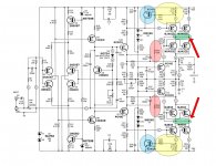
edit: here's the protection circuitry of a tiger 250. The yellow and blue hilite the current sense circuit, it clamps the drive to the upper and lower output pairs. Note the pink 22k resistors, they are the foldback part, if the output is further away from a rail, it reduces the drive to the transistors of that rail.
However, there is a severe error in the schematic as provided in the initial builds. Note the green hilited jumper between emitters Q16/18 and Q21/23. That jumper prevents those transistors from sharing properly, so slight mismatches there will cause runaway. If you own one of these puppies, make sure those green jumpers go away.
pps..almost forgot, the resistor across Q16 and 21...make them 200 and put another pair at 18 and 23.
Attachments
Last edited:
JN
I wanted to leave it at a level you, SY and Scott can handle! Ever notice the diodes from the output back to the supply rails?
(The tiger doesn't have those, but it has a fuse outside the feedback loop. That alone will cause several % distortion at high levels.)
I did a stadium where all of the amplifiers were Crown MA5002's. I would have used 3600's but the wouldn't take the DSP card.
Now I couldn't get enough level on the tweeters. The clip lights on the amps pretty much stayed on. The protection circuits made horrible noises. I hooked up my current probe to the drive lines and was reading more than 100 amps on my scope! I then realized that the clip light on the current probe was also lighting up! I switched it to the higher range and found the peak currents were around 110 Amps. Into a 4" compression driver!!! Seems there was a C-L protection network before the compression driver.
Since everyone here hates questions, what do you think was happening?
Now the designer used QSC amplifiers in his design and found his network boosted acoustic output. Why?
So for quality reproduction protection circuits are often omitted, and either more output devices or a power supply that can't blow the outputs.
Last edited:
Marantz PM-15S1, 1 pair of A1303/C3284 (125W TO3P) and >50V rails.
Protection allows 15A peak output current, rest is handled by a TA7317P chip.
Want Marantz with TA7317P and larger underwear, buy 6-pair A1216/C2922 monaural MA-9S2's. (sets one back $15k though)
So?
How do you get away with that? On any serious basis?
Yah right. This from the person who measured the inductance of a wire inaccurately to the tune of more than 3 orders of magnitude error, and then argued that it didn't matter????JN
I wanted to leave it at a level you, SY and Scott can handle!
Does the phrase "lack of credibility" mean anything to you??

Ever notice the diodes from the output back to the supply rails?
Duh.
What else, teach??
I did a stadium where all of the amplifiers were Crown MA5002's. I would have used 3600's but the wouldn't take the DSP card.
Now I couldn't get enough level on the tweeters. The clip lights on the amps pretty much stayed on. The protection circuits made horrible noises. I hooked up my current probe to the drive lines and was reading more than 100 amps on my scope! I then realized that the clip light on the current probe was also lighting up! I switched it to the higher range and found the peak currents were around 110 Amps. Into a 4" compression driver!!! Seems there was a C-L protection network before the compression driver.
Since everyone here hates questions, what do you think was happening?
Lack of competence on the part of the system installer comes to mind..
😉
So for quality reproduction protection circuits are often omitted, and either more output devices or a power supply that can't blow the outputs.
Scary, isn't it?
jn
ps..you need to learn how to use emoticons to express tongue in cheek.
pps. fuses outside the feedback loop causing distortion?? Give me a break. First, it's a 10 amp fuse. Second, it's a freakin tiger for goodness sakes..who cares about distortion!! Thirdly, I always turned the bias OFF...zero, nada, no quiescent current!!! I pushed the livin daylights outta these things, I do NOT want thermal tracking issues poppin my fuses in the middle of a party or gig.. Not listenable at home btw, where I use a coupla hundred milliwatts for normal listenin.
Last edited:
- Status
- Not open for further replies.
- Home
- Member Areas
- The Lounge
- John Curl's Blowtorch preamplifier part II