I am curious regarding this, many of the new packages are bottom terminated with the die mounted onto a copper interposter (thermal pad) that is usually tied to ground. These newer packages allow much better control of the device temperature, with the correct layout and use of thermal vias etc.
Me too.
Either the silicon has been designed such that the substrate is ground, or the intermediate packaging isolates it.
Again, scott's the best source for that one.
Thermally, you get more bang for the buck if you keep a hard metallic path from the chip backside as far out as possible, with electrical isolation as far from the chip as possible. That reduces the heat flux density through the poor thermal conductivity of the grease and isolating material.
jn
Thank you for your nonsense. So I'll repeat what has already been said for those who missed it.
The statement about impedance is from the AES standard. A loudspeaker's rated impedance is twice the minimum impedance.
Have you ever measured an audio power amplifier? I have never seen one that perfectly doubles maximum power going from 8 ohms to 4 ohms. Do you have one with a regulated power supply?
Ed
I hope you will rethink of the ‘sostenuto’ in your response. It does not fit the composition.
I consider technical matters far less important than communication attitude among members here. I hope for the latter to streamline and ask you for the former: Where did you find this doubling in impedance? I searched and didn’t find it
It is not in AES2-1984 (r2003) (*)
In ‘Sound System Engineering’ by Don Davis (2nd Ed.) it says: "Normal specified Z is the lowest reading just above resonance of the device"
At an online source Ι read: "Rated impedance is 1.17*DCR"
Nothing in old text books (H. Olson, L. Beranek)
Have you ever measured an audio power amplifier? I have never seen one that perfectly doubles maximum power going from 8 ohms to 4 ohms. Do you have one with a regulated power supply?
All the amplifiers with unregulated PSU at the output stage that I have measured, double their power from 8 to 4 Ohm. Perfect doubling at full power may be limited by the capabilities of the PSU.
George has provided his estimate that a MM cartridge can actually produce as much as .880 Volts peak.
880mVp (+42dB above 5cm/sec) is my choice for worst case (considering mild cartridge maladjustment) preamp input overload margin.
If the cartridge is properly attached to headshell and adjusted to the arm, I don’t think that it can ever output signal higher than the equivalent of +36dB above 5cm/sec
George
(*) It only asks specifying "Zmin to a stated tolerance and the voice-coil temperature at which the measurement was made.) Normal practice is for this measurement to be made at 25 ± 5 °C."
Last edited:
Me too.
Either the silicon has been designed such that the substrate is ground, or the intermediate packaging isolates it.
Again, scott's the best source for that one.
Thermally, you get more bang for the buck if you keep a hard metallic path from the chip backside as far out as possible, with electrical isolation as far from the chip as possible. That reduces the heat flux density through the poor thermal conductivity of the grease and isolating material.
jn
I mean the SMD packages soldered directly to the PCB, excellent thermal conductivity, but do work best with multilayer boards with lots of copper. Though by using thermal vias and having the same copper on the bottom you can bolt on heat sinks or have the case made with integral heatsinks and fins. Some of the new FET packages are pretty cool as well with thermal paths both top and bottom of the device, but I do not know how good they would be for audio, there is an increase in capacitance due to the packaging over the older types of package.
Last edited:
Mike, your verbage seems to agree with jan's, from what I can see. 😕 jn
I'm first to admit my communication skills are a bit challenged, but my thought and Jans are not the same. His, as I interpreted it, was that we must build on the current state of the art to evolve into the next level. My intended thought was: once you have the skills and a sonic goal in sight, applying other designers ideas as a foundation could limit what is possible.
Mike
You make a good point, Mike. It is well known that 'conventional' understanding can sometimes limit progress. There are many stories of people 'not knowing enough not to try something new' who make the breakthrough. Of course, total ignorance of a subject may never get you anywhere as well.
My approach is both learning everything I can from the engineering level, but following what seems to work to make better audio products. Often, I am surprised what actually does work, but I will not ignore it, because it defies 'proof' as demanded by many here.
My approach is both learning everything I can from the engineering level, but following what seems to work to make better audio products. Often, I am surprised what actually does work, but I will not ignore it, because it defies 'proof' as demanded by many here.
George,
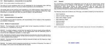
The current AES2-2012 defers to IEC 60268, if you PM me an email I can send you a bit more, but it can't and won't fit here. (IEC-5 now says "The lowest value of the modulus of the impedance in the rated frequency range shall be not less than 80 % of the rated impedance. If the impedance at any frequency outside this range
(including d.c.) is less than this value, this shall be stated in the specifications.") Note it now includes DC! So this fall when we meet again, I'll see what people are really doing.
The unregulated power supply in a power amp of course drops under load, however as most of the power amplifiers being discussed have global feedback that corrects for any error until you run out of power.
If I tune up a sound system at a level of 70 dba (This is usually enough to give me 20 db s/n) and then raise the level to 90 db the FR curve giggles by about 1 db. Going up to 105 it is more like 3-5 db. As Fletcher and Munson showed the ears' frequency response is level sensitive. The point being when you check a loudspeakers FR it should be at the intended output level after it has warmed up.
Now in the case of MM output level the preamp in LA vol 4 by Gary Galo (Want to repeat that as my circuitry memory failed me before!) uses a gain of 100 to avoid too much load on the output of the first gain stage amplifier. (Yes it was eq'd after the first amp.) So even with 22 volt rails the input signal would need to always be below 200mV to avoid undue distortion. So it looks like a current buffer and lower gain would be useful.
Last edited:
Me too.
Either the silicon has been designed such that the substrate is ground, or the intermediate packaging isolates it.
Again, scott's the best source for that one.
Thermally, you get more bang for the buck if you keep a hard metallic path from the chip backside as far out as possible, with electrical isolation as far from the chip as possible. That reduces the heat flux density through the poor thermal conductivity of the grease and isolating material.
jn
It varies, SOI parts are typically isolated and grounding is OK. Junction isolated parts can require the back tied to a supply, not always V-.
Last edited:
Thank you.... I will read them and then see what I can do with the downloads. The idea to use all thier affects software means they can deconvolve accurately.
THx-RNMarsh
The claim of 100% perfect results has to be false. Noise in the data set is the bane of any deconvolution algorithm since it is in the class of finding the inverse type of problems. The inverse of a very small number contaminated by noise can blow up. Search for Weiner Filter which is based on the exact inverse, i.e. think convolve = multiply in the frequency domain so deconvolve = divide.
Deconvolution (with impulse response) is extremely sensitive to interferences and noises of all kinds - as one would expect by definition. Qualified user needed.
George,
The current AES2-2012 defers to IEC 60268, if you PM me an email I can send you a bit more, but it can't and won't fit here. (IEC-5 now says "The lowest value of the modulus of the impedance in the rated frequency range shall be not less than 80 % of the rated impedance.
Thank you Ed.
I found the relevant paragraph on the web. Max difference of 20% is logical and acceptable.
Today I was searching in the “AUDIO Annual Equipment Directory” from 1988. There were indeed many speakers with Nominal Imp/Minimum Imp 2:1 ratio (almost all of USA origin, why?)
So even with 22 volt rails the input signal would need to always be below 200mV to avoid undue distortion.
Going through the same 1988 Audio Equipment Directory, there were a lot of preamplifiers, integrated amps, receivers that were listed with MM input overload below 150mV.
No wonder that some MM cartridges got a bad name and some got red roses (9.5mV@5cm/sec to 1.5mV@5cm/sec -a 16dB difference in output- can explain a lot)
George
Attachments
Last edited:
Yes, this is very much the approach. Weird things work, or cause changes in the sound ... and the only intelligent approach is to take these on board, and work with them. Over time understanding of what the underlying mechanism is starts to dawn on one, and a more considered, "engineering" approach can be used.My approach is both learning everything I can from the engineering level, but following what seems to work to make better audio products. Often, I am surprised what actually does work, but I will not ignore it, because it defies 'proof' as demanded by many here.
Ignoring them just gets one stuck in a rut, and the sound of much audio makes it obvious how deep that rut is ...
dvv
So what happens there when the speakers heat up? Are we now asking our amps to work into sub 3 Ohm impedance
No, because the resistance rises as they heat up.
@ ticknpop
You can get an Amp with 14000W in 1 U 😱
You make a good point, Mike. It is well known that 'conventional' understanding can sometimes limit progress. There are many stories of people 'not knowing enough not to try something new' who make the breakthrough. Of course, total ignorance of a subject may never get you anywhere as well.
Hey John, to my mind the point is, and this is a 60's thing, question authority.
I want to thank you for you input here over the years (not to forget the many other serious contributors to the conversations) I have learned a lot.
Mike
Deconvolution (with impulse response) is extremely sensitive to interferences and noises of all kinds - as one would expect by definition. Qualified user needed.
Qualified user... I ain't. BUT, if the software writers intended somewhat less than totally qualified and knowing what is a bad result and rejecting it - etal - maybe something can be done to pick one's curiousity and learn something about the original source? I just need to know where the pit-falls are to avoid. I wouldnt use low level signals. It will be good to get a few waveforms and test and listen to certain changes from original to what the end user gets. of course, if one had the original signal/source to compare against, that would work also. That usually isnt available.
There is a lot of compression in recordings..... and the process does more than compress... generates distortion products in the process. How to remove it and get back to or at least a closer approximation to original? Need some data and clues to begin to guess what to do or which algorithm to use as best match. Wonder if this is available in some form in DAW software. or the above mentioned software. hmmm.
THx-RNMarsh
Last edited:
I spent some time, a while ago, playing with this - and it would be possible. The algorithms, and processing, need to be quite sophisticated but it certainly is doable. As a test case, I used an extremely overcooked, locally produced pop number - used as the theme tune for a TV show in fact - and manually played with parameters, using various criteria for judging the settings. The end "product" was vastly better in terms of the subjective impact, and certainly didn't appear to suffer distortion from the manipulation - the drums, which were buried under heavily compressed guitar sound, emerged unscathed and the production was now in far better balance.There is a lot of compression in recordings..... and the process does more than compress... generates distortion products in the process. How to remove it and get back to or at least a closer approximation to original? Need some data and clues to begin to guess what to do or which algorithm to use as best match. Wonder if this is available in some form in DAW software. or the above mentioned software. hmmm.
THx-RNMarsh
I spent some time, a while ago, playing with this - and it would be possible. The algorithms, and processing, need to be quite sophisticated but it certainly is doable. As a test case, I used an extremely overcooked, locally produced pop number - used as the theme tune for a TV show in fact - and manually played with parameters, using various criteria for judging the settings. The end "product" was vastly better in terms of the subjective impact, and certainly didn't appear to suffer distortion from the manipulation - the drums, which were buried under heavily compressed guitar sound, emerged unscathed and the production was now in far better balance.
very good.... ask and ye shall receive 🙂
What software do you use/recommend so that I could do something similar to what you did?
THx-RNMarsh
Reaper, REAPER | Audio Production Without Limits, which is a very sophisticated and powerful package is available to download, to assess for purchase. The effects allow for very fine tuning of the parameters for compression, and decompression - just playing with the settings in a single module, in a single operation, will do a great deal of the work - I found it very satisfying to play with ... 🙂
Thanks Mike, for your input. It is pleasant to hear that somebody is getting something out of these discussions. One might think that Bose won the contest, and hi fi was not important anymore. '-)
While I still design the best products that I am able to do, I don't do many direct listening tests anymore, except for myself.
It would be useful to better correlate what we hear with what we measure, but I'm afraid that normal distortion tests won't show much more than they have for decades. Yet, I'm pretty sure that we will find that we are not fooling ourselves, and that the differences that still appear, especially with long term listening, will be better understood in future, but it might take a more sophisticated approach to the measurements to get any obvious results. You know, it is difficult to measure all differences in electronics with the same sort of electronics that makes up the test equipment, itself.
In other words, if you test an op amp with another similar op amp (in the test equipment) why doesn't the test equipment itself fail to measure properly? It would appear that we are measuring the wrong thing. (This is not my original idea, but Richard Heyser's, it's a shame that he isn't with us today.)
John Curl wrote:
"... It is pleasant to hear that somebody is getting something out of these discussions..."
Oh, you'd be surprised, John, how much there is to be had from these discussions. Directly (here) or indirectly (links, pointers).
Just yesterday, Richard sent me looking at other topics related to power amps, and while I saw little I had not seen and/or used before, it was really good to see folks enjoying themselves so. Thanks again, Richard.
Ultimately, it just feels GOOD to chat with you guys, despite the inevitable naysayers, who seem to plague each and every forum. But over time, one does develop an automatic ignore filter.
- Status
- Not open for further replies.
- Home
- Member Areas
- The Lounge
- John Curl's Blowtorch preamplifier part II