Now to continue to drive everyone nuts, let us start the next round! (SY you're back in.) If we think that noise versus distortion is a trade off in low level amplifier design using ICs, then can we apply some engineering skills to balance this.
Some might say the record noise is above this so don't worry about it. Others might insist on a double blind test to see if it matters. JC just compares one preamp to another to see if he can hear a difference.
Now Pavel would say use a buffer, which is one approach, but let's see if we can apply some perception research to get a better balance.
One item of interest would be masking. If we have a pure sine tone 100 db below the noise level it would not be perceived by humans. There is reasonable evidence that with the noise level equal to the tone it would be an issue.
Somewhere around 20 to 30 db of masking would hide the tone. So we now have a target of designing for the distortion to be 20 db below the noise level.
An audio engineer would also know that the resonant frequency of our hearing is around 3,500 to 5,000 hertz.
The distortion of an LME49990 is around .00001% in this range as long as we stay well away from clipping. (15 volt rails 2,000 ohm load, 3 volts out.)
So the first question is what noise bandwidth should we use as a design value for a second harmonic distortion of a 4,250 hertz fundamental?
(SY you're back in.) If we think that noise versus distortion is a trade off in low level amplifier design using ICs...
If I don't accept that axiomatically, does that mean I'm back out? 😀
If I don't accept that axiomatically, does that mean I'm back out? 😀
Can you play nice and answer the question?
Now we are almost there! The next question should be easy, what is the impedance of the phono cartridges? Or in other words how many nv/sqrt(Hz) will the cartridge produce?
Re arguments (*) 😀
Re noise
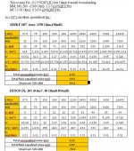
Ed see att.1.
SY is right (L affect cartridge noise a lot) but I see your point at post #53555.
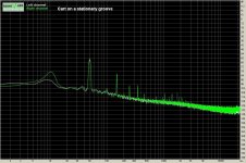
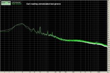
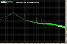
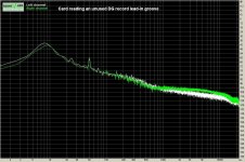
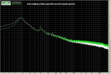
I would be with you but as I’ve said, for me this noise is of no importance (**) when a cartridge is reading a groove.
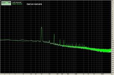
Rest attachments (pls see the broadband spectrum, not the 50Hz related peaks): DENON DL103 plus a 23.5dB head pre (***), plus Hagerman Buggle RIAA pre (40dB/1kHz), plus passive volume control. 0dB=1.286Vrms
George
(*) Socrates was
an outlaw , illegally practicing a midwife’s art to give birth to the latent knowledge (he was himself son of a midwife)
a serial killer, murdering wrong assumptions
an anarchist doubting and putting under examination long held beliefs
a man married to Xanthippe
(**) Not only due to it’s low amplitude compared to record surface noise but due to it’s smooth spectrum. Our head (mine at least) doesn’t notice it.
I would consider it a problem when it starts to modulate, that is when the cartridge sees a heavily varying preamp input impedance. This leads to my third pre amp criterion Stable input impedance. See how Dimitri is dealing with this problem for the last 25 years or so
http://www.angelfire.com/az3/dimitri/images/riaa.pdf
Supply Bootstrapping Reduces Distortion In Op-Amp Circuits | New operational amplifiers optimized for high-performance audio and ultrasound applications combine extremely low total harmonic distortion plus noise (THD+N), -130 dB, with large output vo
JFET Follower Amplifier Cancels Distortion | Analog content from Electronic Design
(***)
Attachments
-
 1 Answer.JPG91.4 KB · Views: 251
 -
 2 Cart on rest arm.JPG146.9 KB · Views: 253
 -
 3 Cart on stationary groove.JPG148.4 KB · Views: 248
 -
 4 Cart reading unmodulated test groove.JPG149 KB · Views: 244
 -
 5 Test rec lead-in.JPG150.5 KB · Views: 249
 -
 6 Ravel lead-in.JPG151.6 KB · Views: 94
 -
 7 Orf lead-in.JPG152.1 KB · Views: 94
Re arguments (*) 😀
Re noise
Ed see att.1.
SY is right (L affect cartridge noise a lot) but I see your point at post #53555.
I would be with you but as I’ve said, for me this noise is of no importance (**) when a cartridge is reading a groove.
Rest attachments (pls see the broadband spectrum, not the 50Hz related peaks): DENON DL103 plus a 23.5dB head pre (***), plus Hagerman Buggle RIAA pre (40dB/1kHz), plus passive volume control. 0dB=1.286Vrms
(**) Not only due to it’s low amplitude compared to record surface noise but due to it’s smooth spectrum. Our head (mine at least) doesn’t notice it.
I would consider it a problem when it starts to modulate, that is when the cartridge sees a heavily varying preamp input impedance. This leads to my third pre amp criterion Stable input impedance. See how Dimitri is dealing with this problem for the last 25 years or so
http://www.angelfire.com/az3/dimitri/images/riaa.pdf
Supply Bootstrapping Reduces Distortion In Op-Amp Circuits | New operational amplifiers optimized for high-performance audio and ultrasound applications combine extremely low total harmonic distortion plus noise (THD+N), -130 dB, with large output vo
JFET Follower Amplifier Cancels Distortion | Analog content from Electronic Design
(***)
Great stuff george, now, what would cause a phono stage to not have a stable impedance ..?
For the esoterics (engineering details) see Dimitri’s elaboration.what would cause a phono stage to not have a stable impedance ..?
Acc to my simple mind, it is mostly the interaction of the RIAA feedback network with the cartridge.
A buffer solves this problem (see an MC head amp. Also the first buffer with a passive RIAA scheme for a MM cartridge)
George
Last edited:
George,
The issue of distortion increasing with loading in IC op amps shows up in any low level circuit.
But you are getting too far ahead. The issue at hand is noise masking. Right now it is easier to look at flat FR masking before getting into vinyl noise and EQ. Now since the example is JC's work he uses passive eq, placing more emphasis on the first stage preamp.
(Distortion if you look carefully actually begins to rise above 2 volts into 2000 ohms.)
So the question on the floor remains. For design values what should the noise bandwidth be?
Have you established the premise?
I am aware of the bandwidth you chose. Would JJ pick the same?
I am aware of the bandwidth you chose.
For what?
Would JJ pick the same?
For what?
For what?
For what?
SY are you getting old enough to be..: oh I forgot the issue.
The discussion is what noise level is equal to a distortion product. In particular I picked a distortion product of 8500 hertz. Now Harvey Fletcher in the 1930-40s published work showing that as noise level increases mask also does up to a point. He also came up with a model of this based on bandwidth which are called critical bands. This was farther refined into equivalent rectangular bands. All of this is very basic to our understand of how we hear.
So when we want to do our design this is a very basic issue. Now does anyone want to sugged what equivalent bandwidth we should design around?
(Hint 1/3 octave around the target frequency of 8500 hertz would be a good guess although with a bit of research the number could be a bit more acurate.)
George
(*) Socrates was
an outlaw , illegally practicing a midwife’s art to give birth to the latent knowledge (he was himself son of a midwife)
a serial killer, murdering wrong assumptions
an anarchist doubting and putting under examination long held beliefs
a man married to Xanthippe
...
In other words, a great guy to have around. Perhaps married to the worng woman. 😀
George,
Since you want to get ahead of the discussion, why don't you look up Harry Fletcher's research on how loud a broadband signal had to get to mask a tone. (I think he used 2,000 hertz at 10 db.)
This may help to explain why a non-harmonically related distortion can stand out so much.
P.S. previous post typed on a cellphone with too many bandaids on my fingers! (While sanding the piece flew out of my hands!)
Last edited:
Why is RIN not s measurement criteria in audio? It is in just about every other analog system. For instance our analog optical transmitters have a RIN between -167 and -172 dB
Why is RIN not s measurement criteria in audio? It is in just about every other analog system. For instance our analog optical transmitters have a RIN between -167 and -172 dB
Because unlike monochromatic lasers audio covers a wide bandwidth and other measurements such as intermodulation distortion will show up gain nonlinearities. Although relative intensity noise would be a very interesting measurement on a pipe organ! (The mechanism to cause RIN is present in the organ, but rarely in a linear amplifier.)
MY OPINION ONLY!!!
Since you want to get ahead of the discussion, why don't you look up Harry Fletcher's research on how loud a broadband signal had to get to mask a tone. (I think he used 2,000 hertz at 10 db.)
Socratic question: what's the elephant in the room that you're ignoring?
Switching bias; can you say that John?
I don't know, how do you define it?
Sorry, I wasn't clear.
* High-speed bias servo, for Class A efficiency. ...By applying a bias current only in the amount needed at any given time. ...For high efficiency and no switching distortion. ...Class A/B amp.
Socratic question: what's the elephant in the room that you're ignoring?
What room are you talking about?
- Status
- Not open for further replies.
- Home
- Member Areas
- The Lounge
- John Curl's Blowtorch preamplifier part II