So whats the issue , the 100 hrs or the bloom ....
Both 🙄 if I want "blooming" I'll take up gardening
Capacitors don't need 100 hours break in, same as all passive components and active ones and wires and PCBs, but its a good get out of jail free scam:
If it sounds c**p out of the box it is because it need 100 hours break in, meaning you ears will adjust, only in high end esoteric audio...
Exactly. Funny how it's always the component that "breaks in" and never the listener's ears/brain adjusting instead 😉
Mooly;3903323 My maths isn't up to calculating that without researching it :D[/QUOTE said:I have various PCB calculators for doing high speed and getting electrical lengths matched, Jneutrons' input would be interesting here as I suspect the construction may have a part to play in the speed reduction.
For the total length, I multiplied 2816 turns by 18mm (RG58 diameter is 6mm) and used their figure of 1300ns delay.
See your up early . My preference polyprop reasonable cost the metal is the big one in caps . I prefer copper as a metal. Just saying much better than tin and alluminium but cost is high no economy of scale.
Sorry to Joachim, I meant to say that Samuel found ordinary commercial caps that started out not needing improvement so I would just go with them.
Some quick maths and I get a speed of 0.026ns/mm for the delay line! for microstrip its 0.006ns/mm either my maths is wrong or the construction slows the signal propagation down...
I have various PCB calculators for doing high speed and getting electrical lengths matched, Jneutrons' input would be interesting here as I suspect the construction may have a part to play in the speed reduction.
For the total length, I multiplied 2816 turns by 18mm (RG58 diameter is 6mm) and used their figure of 1300ns delay.
The device is a combination of effects beyond simple length prop.
The wound wire has a 15 nH per foot inductance added to by the solenoidal inductance. The capacitance per foot is a combination of cap to core and cap to added shield.
Both effects conspire to increase the per length inductance and capacitance, so the prop velocity slows down as V = 1/sqr(LC).
jn
You may also find this interesting:
http://sites.ieee.org/ctx-emcs/files/2010/09/Archambeault-Ground-Myth.pdf
Nice, thanks.
Page 8: He uses the skin depth approximation formula. Great for the frequencies of interest in his article, not good within the audio band and 12 awg wires, the first three frequencies of his table applied to round wires would be in error, but better for infinitely wide flat conductors.
Page 10: Of note is the two frequencies where the drop stalls, 5 Ghz and 30 Ghz. If those are actual measurements, I'm suspecting the 5 is the end of the surface finish of the lines and the 30 is more subtle lattice/phonon goop I never understood back in grad school.. If they are modeled, well, "nevermind".
Page 15: He equates current flow through metal with inductance. That is incorrect in that any current flow has a consequent magnetic field hence energy storage. Ampere's law does not consider the material the current is passing through, only the current density and profile.
Page 20: If stuck with an axial cap for decoupling, put it vertical, it's bottom lead through the board to the bottom plane. Run a braid over the cap body, connect to the top lead, and the braid at the pcb top surface. This eliminates all inductive field outside the braid, therefore outside the cap.
Page 57 and 61: He switches to scientific notation for frequency. I ran outta fingers, so couldn't figger the graph out.😕
Page 102: Note how the pseudo-shielding around a pin drops the inductance. In the limit, it's a cylindrical shield that would work the best.
This slide show is absolutely excellent, my points are applicable to audio for the most part which was not his target.
I'm keepin this in my documents.
Thanks Marce.
jn
Last edited:
The device is a combination of effects beyond simple length prop.
The wound wire has a 15 nH per foot inductance added to by the solenoidal inductance. The capacitance per foot is a combination of cap to core and cap to added shield.
Both effects conspire to increase the per length inductance and capacitance, so the prop velocity slows down as V = 1/sqr(LC).
jn
Cheers Jn I knew you'd give me the pointers to go and look at🙂
Thanks to those who answered me seriously about recommended caps.
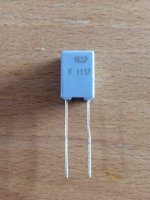
Of course, I normally use Rel RT Polystyrene caps for both power supply bypassing and EQ, but they are film-foil, and too large for a much cheaper design. That is why I asked. However, the metalized polypropylene cap seems to be a winner.
Of course, I want low DA, almost zero distortion, and good tolerance is still necessary. The real tradeoffs here, may as well be lead material (magnetic?) and internal attachment. I trust the Germans, more than most anyone else to do a good job with this.
Wima may be just as OK, but they do seem to be larger and probably harder to source. We are always sourcing Vishay owned parts, so that would be easier.
I DO believe in cap break-in for EXTRA-GOOD caps. Scott can avoid it with the regular stuff, but I won't.
Scott can avoid it with the regular stuff, but I won't.
Why me. I've had test jigs that took a full day to settle down, but I was virtually counting electrons.
You said yourself that you won't bother with the better caps that need to be broken-in. I will, and do it all the time.
You said yourself that you won't bother with the better caps that need to be broken-in. I will, and do it all the time.
Samuel found caps -160dB "out of the box" so why bother.
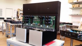
Cool, I'll take one of the 34K euro 100W amps for my DQ10's and see if it betters my Hafler 220's. Chances are I'll keep my money in local real estate.
Last edited:
My brush with Vitus at the hifi show was a positive one - it produced music, rather than having the typical hifi amplifier sound ...
Every cap, Scott? I just measured one today that measured higher than -100dB. Of course, there is also DA and vibration sensitivity. However, the bottom line is making a successful product, both in measurement AND sonic quality. Because I do both, I am successful at what I design.
The real tradeoffs here, may as well be lead material (magnetic?) and internal attachment.
Wima may be just as OK, but they do seem to be larger and probably harder to source.
My 0.1uF-MKP-1837s are non-magnetic. Burklin is a good source for Wima including 1%-FKP 2(5mm. LS as well).
Attachments
Cool, I'll take one of the 34K euro 100W amps for my DQ10's and see if it betters my Hafler 220's. Chances are I'll keep my money in local real estate.
34k In Cambridge Mass ? What you buying an Outhouse ...🙂
I heard Classe is now manufactured in China and yet still commanding big $$. Big difference between your DH220 and a vitus, really big ..
I think everone still remember this :
http://usr.audioasylum.com/images/3/38588/Lyra_Connoisseur_Line_5_b.png
Jonathan put a whole PCB full of MKP caps (in parallel) right next to the preamp / regulator.
The PSU is in another box.
I wonder what John's comment on this might be ?
Patrick
http://usr.audioasylum.com/images/3/38588/Lyra_Connoisseur_Line_5_b.png
Jonathan put a whole PCB full of MKP caps (in parallel) right next to the preamp / regulator.
The PSU is in another box.
I wonder what John's comment on this might be ?
Patrick
- Status
- Not open for further replies.
- Home
- Member Areas
- The Lounge
- John Curl's Blowtorch preamplifier part II