It's been raining in California, that means everyone goes outside and looks up at the sky in wonder. Nothing gets done here when it rains, we seldom see the wet stuff. 😀 😱
Are we all 'gassed out', I hope so. Let's try to talk about audio electronics instead, can't we?
Interesting, for how many days will an actual technical exchange stop this thread?
I guess that was some serious gas ....
OK, here goes: This is a design concept that has been around for about 45 years, and is often used in hi end. It is perfect for very high power amps and fully balanced preamps. What I am putting up at the moment are SIMPLIFIED MODELS of the real thing, 2 are preamps, 1 is a power amp.
Attachments

Scott, you have been part of the problem. I will start a new technical discussion when I fix some scanning issues.
OK, I tried to answer a question maybe I should not bother.
Scott, thank you, I've noted your answer but was waiting for more input from others.OK, I tried to answer a question maybe I should not bother.
In regard to quasi sat - isn't this the property of power BJTs mostly? I was talking about the small signal transistors.
Scott, thank you, I've noted your answer but was waiting for more input from others.
In regard to quasi sat - isn't this the property of power BJTs mostly? I was talking about the small signal transistors.
No, this can appear when least expected.
OK, here goes: This is a design concept that has been around for about 45 years, and is often used in hi end. It is perfect for very high power amps and fully balanced preamps. What I am putting up at the moment are SIMPLIFIED MODELS of the real thing, 2 are preamps, 1 is a power amp.
And we come full circle, I do like the star trek epsode that has a time loop that goes around and around.
While this topology originated at least 45 years ago, it is in two of my well known designs of today, in both the Parasound JC-2 and the Constellation phono preamp, both award winners.
It makes a pretty good power amp too.
This topology cannot be easily duplicated in IC's.
Both Nelson Pass and Charles Hansen make similar, if not more sophisticated designs like this as well.
It makes a pretty good power amp too.
This topology cannot be easily duplicated in IC's.
Both Nelson Pass and Charles Hansen make similar, if not more sophisticated designs like this as well.
Now, the reason that I put this design up, once again, is to show why it is still used today by several 'high end' designers:
It is 'simple' yet 'elegant' with a minimum of extra devices in the actual audio path.
It can be made with either bipolar, jfets, cmos, or mosfets, and often with a combination of different devices.
Being fully balanced, input to output, it is one of the most linear (from and audio point of view) design possible. There are no single ended drivers somewhere hidden into the design.
The balanced bridge output allows for much more powerful designs (up to 4 times) compared to a typical single ended output, or the use of lower voltages, in order to reduce component stress.
It always gives double the slew rate than a single ended design.
Therefore, slew rates of 1000V/us have been made with a power amp, because of this advantage.
Now let us look at the simplest version first:
Attachments
Thanks for bring this thread back to circuit design.Now, the reason that I put this design up, once again, is to show why it is still used today by several 'high end' designers:
It is 'simple' yet 'elegant' with a minimum of extra devices in the actual audio path.
It can be made with either bipolar, jfets, cmos, or mosfets, and often with a combination of different devices.
Being fully balanced, input to output, it is one of the most linear (from and audio point of view) design possible. There are no single ended drivers somewhere hidden into the design.
The balanced bridge output allows for much more powerful designs (up to 4 times) compared to a typical single ended output, or the use of lower voltages, in order to reduce component stress.
It always gives double the slew rate than a single ended design.
Therefore, slew rates of 1000V/us have been made with a power amp, because of this advantage.
Now let us look at the simplest version first:
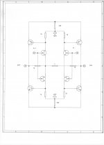
Sure. There might be a mistake, IMO 1k resistors should be connected to ground. Then it is a design without global NFB and R1 sets gain - local feedback.
Last edited:
Scott, thank you, I've noted your answer but was waiting for more input from others.
In regard to quasi sat - isn't this the property of power BJTs mostly? I was talking about the small signal transistors.
If you look at the pair ostripper just recommended in the CFA thread you will see it in spades on the npn.
You could replace the JFETs with CFA diamond input stages as well - much more complex- but you can get matched SMD devices ( 2mV and 10% hFE) from quite a few suppliers, avoiding the JFET supply issues.
Let us not confuse the situation PMA. There are lots of permutations and combinations that are possible and even practical, but first things first.
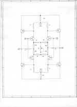
This SIMPLIFIED schematic is not a commercial schematic. It would be difficult to for anyone but an amateur to make this, one off, because the input jfets have NO bias control. They simply run at Idss which will vary all over the place, IF not carefully selected. I would say that an Idss range of 2-4 ma would be mandatory in this example, and close matching as well.
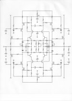
However, this 'primitive' schematic shows the ADVANTAGES of this sort of topology, Being: Very low noise possible, as there are no input series resistors needed to complete the feedback loop, fully balanced feedback is possible with only 3 resistors to set the gain, and 2 fully uncommitted inputs available with a minimum of active parts. This noted, it might be better to look at a more 'realistic' schematic with the same topology.
However, this 'primitive' schematic shows the ADVANTAGES of this sort of topology, Being: Very low noise possible, as there are no input series resistors needed to complete the feedback loop, fully balanced feedback is possible with only 3 resistors to set the gain, and 2 fully uncommitted inputs available with a minimum of active parts. This noted, it might be better to look at a more 'realistic' schematic with the same topology.
- Status
- Not open for further replies.
- Home
- Member Areas
- The Lounge
- John Curl's Blowtorch preamplifier part II