You can't- it's not anything like a capacitance. There's a fundamental bass resonance, followed by a plateau in impedance, then a dip and rise from the transformer's interaction with the panels. Note that the inductance dominates above 20kHz.
SY, what speaker has a high C load that it gives to a power amp?
That was John's straw man, not mine. Ask him. I was just answering his question. 😀
edit: My guess is that cable capacitance will dominate above 100-500kHz for most practical speakers and cables. A reasonable wire might show 20-30pF/ft, a pathological one "designed" for fashion might be 4 or 5 times higher.
edit: My guess is that cable capacitance will dominate above 100-500kHz for most practical speakers and cables. A reasonable wire might show 20-30pF/ft, a pathological one "designed" for fashion might be 4 or 5 times higher.
The usual somewhat equivalent load capacitance for the Quad speaker is 2uf (in series with 2 ohms)
Of course there are much bigger electrostatic speakers that are available.
Of course there are much bigger electrostatic speakers that are available.
Good info John on the output pairs. Lynn Olson in his thread in the speaker section has been in favor of no more that two output devices, for reasons that he goes into in the thread. Your experience designing power amplifiers speaks volumes.
Lynn was right. Non matching paralleled output will degrade the low level resolution. But he was wholely or partially wrong when he said that the only reason to parallel output device is to get higher wattage. 60w still needs parallel device for sufficient current drive.
So both Lynn and John were right. In my situation (non tube am and passive xo) current or low z is more important.
What is the impedance plot showing? 5uf?
No. It's a complex (in the "not simple" meaning of that word) impedance, looks like an inductive rise above 15kHz. Calling that a capacitance is not very accurate.
Let us estimate the capacitance loading of this Quad loudspeaker:
about 5uF.
We need very stable amplifiers for this speaker. High feedback factor is a bad thing here.
Attachments
Last edited:
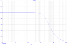
Above 1KHz the impedance looks a lot like the equivalent circuit shown below.Let us estimate the capacitance loading of this Quad loudspeaker:
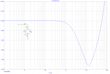
The interesting question is: Why is that inductance there? It's not because Peter Walker couldn't design a decent transformer. It's there to give a much-needed boost at the top end of the frequency response to compensate for the falling response of the ESL panel itself. The third pic below shows the response of this (admittedly oversimplified) circuit.
Now what's the effect of putting 10uH in series whith that? It gives a fairly broad lift to the treble response - roughly 1dB between 10KHz and 14KHz.
Not at all. It illustrates John's point about output coils perfectly, IMHO.straw man
Attachments

about 5uF.
We need very stable amplifiers for this speaker. High feedback factor is a bad thing here.
today many SS amps have unity loop gain intercept over 1 MHz - that's where loading hurts stability - and where ESL step up trnasformer ESR, ESL are already doing a great job as an isolation network
its easy to size outputs, supply so that the amp shouldn't have a problem with 5 uF in the audio band as long as you account for the heat and SOA stress of the 90 degree phase load
It's not because Peter Walker couldn't design a decent transformer.
If there was any implication of this in my post, be assured that it is not intended- PW was a brilliant audio engineer, next to Blumlein perhaps the best ever. Every bit of the ESL57 design was thought through and optimized as part of the overall system, and PW's papers and patents on the subject are models of clear thought and should be required reading.
But you do understand that the amplifiers meant to drive this speaker (including PW's superb amps) had a significantly higher output inductance than 10uh...
The Quad electrostatic speaker is but one example. There are much bigger electrostatic speakers that my amps have to drive.
Also, the NEED for such a large output inductor shows a lack of design stability, that should have been fixed in the circuitry.
Also, the NEED for such a large output inductor shows a lack of design stability, that should have been fixed in the circuitry.
if they still use step up xfmr - to be driven by ordinary amps - then the xfmr parasitics are going to be the limiting high frequency Z, not the reflected panel C at the primary
you really seem to be stuck on this issue too - you keep repeating yourself without the qualifications that others have added - as if you are contradicting them
you really seem to be stuck on this issue too - you keep repeating yourself without the qualifications that others have added - as if you are contradicting them
Stuck on what? JCX? Even the Crown DC-300, designed in the late 70's had only a 2uH output inductance. Why more? Maybe Bob Cordell could give us the answer.
on the example of ESL as a "uF" load to an amp - it simply isn't the case for stability discussion - which is what a few recent posts have been talking about - the required step up xmfr is in the way, dominates the Z seen by the amp by the frequency range critical for stability
any discussion of ESL interaction with the amp above 20 kHz needs to include the step up xfmr parasitics
any discussion of ESL interaction with the amp above 20 kHz needs to include the step up xfmr parasitics
Last edited:
Older, slower devices could cause more HF phase shift so need more protection from capacitive loads. That might explain large inductors in the past.john curl said:Also, the NEED for such a large output inductor shows a lack of design stability, that should have been fixed in the circuitry.
Large inductors in the present might be caused by people who think their customers might be tricked into using high-C speaker cables. A designer who says "don't use such cables" would be technically right but marketeeringly foolish?
Crown got away with 2uH using a 2n3773 quasi output stage. Is there anything worse?
Last edited:
Agreed about PW. I wasn't suggesting any implication, just pointing out that output coils can have a significant effect on frequency response.If there was any implication of this in my post, be assured that it is not intended- PW was a brilliant audio engineer...
I don't know about the Quad valve amps, but do seem to remember the 303 had quite a high output inductance. In the case of the ESL57 that output inductance gives a useful lift to the upper treble.But you do understand that the amplifiers meant to drive this speaker (including PW's superb amps) had a significantly higher output inductance than 10uh...
OTOH, amps that are intended to drive a wide variety of speakers are probably better off without an output impedance that acts willy-nilly as a tone control whose effect depends entirely on what kind of speaker it's connected to.
- Status
- Not open for further replies.
- Home
- Member Areas
- The Lounge
- John Curl's Blowtorch preamplifier part II