Attachments
Last edited:
I think most of us have seen subtractive crossovers before. Some of us have even built them when we weren't busy staring at the ground and drooling.
http://www.diyaudio.com/forums/full-range/121236-favorite-speaker-wire.html#post1484644
I'm starting to make out my Christmas list. What's your drool cup size?
se
I'm starting to make out my Christmas list. What's your drool cup size?
44 long.
There is of course no technical reason why this can't be done. Being a
manufacturer, it is easy for me to provide a listener with two amplifiers with
identical exteriors and differing only in subtle ways. The amplifiers are
delivered blind, and the listener labels them to avoid confusion. They do not
get to see inside, and information regarding the differences is not provided.
The amplifiers are used in the listener's known system for as long as they
like, and upon returning them they tell me what is heard. Later, I can check
that using their labels. The test can be repeated, but care is taken that
the units cannot be identified by external scratches and such.
Anecdotally I can tell you that some people are reliably sensitive to things
that do not stand out in the "usual measurements". Not being very objective
myself, I try to keep these people around.
😎
That reminds me to an experiment i´ve described several years ago in this thread.
Two different preamplifier versions in (almost) identical cases delivered to 5 different listeners within a couple of months. Each listener should evaluate the preamps for some days and choose which one he prefers.
Measured performance was for both versions well below the known thresholds of hearing.
I selected the listeners for their listening habits and was sure that they would prefer the same version as i did, provided that they would hear a difference at all.
All 5 preferred the same preamp version.

Hi Scott,
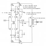
You posted this schematic a while ago and I am trying to make a mental sim of it, but I don´t get it quite yet.
The first question I have is with regard to J6..8. In the way it is drawn, wouldn´t it act as an inverted common mode amplifier? The only way it could work in my head is if J6 would be an nfet and J8 a pfet.
The second question is why the non-inverting side is connected to the rails through resistors R8 and R9, while J2 and J3 share a connection to the rails with the succeeding stage over R6 and R7. If this is to compensate for nonlinear behaviour in J5..8, can you please give a clue as to how this works?
Don't know where to find this? or I'd give it a try!!You could also glue Dick's buffer on instead of the two FET's and see if it still works.
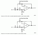
The reason I ask about agreement on the formulas.........
is that many sources use R1 = R2 and C1 = C2
Seems to me that if that is right, (for precise 12 db/oct)
then National is wrong....Or visa-versa
I think this is the right schematic. Check it, those who can, there still might be an oversight somewhere.
My guess why this never took off is because you substract the phase shifted signal that comes out of the low pass filter from the not-phase shifted original.
Perhaps it would work better if you would first run the original through an all pass network that generates an identical phase shift as the low pass filter, before substracting.
But, in that case, you could save an opamp by just using another Sallen-key high pass filter and forget about the whole substraction idea.
My guess why this never took off is because you substract the phase shifted signal that comes out of the low pass filter from the not-phase shifted original.
That's the key (no pun intended) to getting the sums to equal the original, i.e., be "transient perfect". What you lose is the symmetry of slopes.
Sy, you are right.
What it boils down to in my eyes is that you ask from the high driver to correct the phase shift of the low driver. Is that good? No, besides the problem of achieving only a 6dB slope on the high section, this also requirs a bulge in the high filter response around Fx.
Translated into what this does in a speaker: on axis, the speaker may be flat, but at the same time, you will create a powerful lobe off axis around Fx.
Asking ?Bad idea, hitsware
http://sim.okawa-denshi.jp/en/OPstool.php
If C1=C2.......R1=R2 then Q=0.5
If C1=2*C2....R1=R2 then Q=0.707
Last edited:
Before too much speculation is put forth, the problem with the TP crossover is that it is difficult to achieve good enough ACOUSTIC SUBTRACTION to make the crossover effective. However it can work as a subwoofer to woofer xover fairly well. AND it has been used to frequencies of 4KHz and even higher with PROPERLY 'TIME' ALIGNED SPEAKERS, TW0 SPEAKERS (of the same speaker type) PHYSICALLY OR WITH A DELAY ADDED TO ONE SPEAKER, PLACED IN ALIGNMENT WITH EACH OTHER.
Last edited:
- Status
- Not open for further replies.
- Home
- Member Areas
- The Lounge
- John Curl's Blowtorch preamplifier part II

