Which has precisely what to do with
"John Curl's Blowtorch preamplifier part II" ??
More or less just as much as your last two posts

Talking about varying the mains frequency made someone ask me about using differently SHAPED mains waveforms, instead. Has anyone here thought about or tried that?
It might sound crazy at first, but a square wave could work very well. It certainly makes efficient use of the time available in each cycle. And it doesn't have those pesky peaks.
Of course converting to square first would lose at least 30% of the amplitude. But this is probably just an academic exercise, anyway.
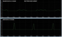
Since it was so easy to do, I tried using a square wave for the AC mains, with my existing lt-spice sim of an unregulated linear supply and power amp pushing a sine signal into a resistive load. I think it was set up for a 270 Hz sine and 100 watts into 8 Ohms. I just used a square wave of the same peak amplitude as the sine I had been using, for the mains, which was about 116 x 1.414.
As you might imagine, rectification of square waves is much more beautiful than with sines. I only did a few quick checks but found that the diode current peaks were about 20% as large and the ripple voltage was about one third the amplitude, and better-behaved than with the sinusoidal mains.
I just thought it was an interesting concept. It's probably not too practical, since it would require an extra stage to convert to square waves.
It might sound crazy at first, but a square wave could work very well. It certainly makes efficient use of the time available in each cycle. And it doesn't have those pesky peaks.
Of course converting to square first would lose at least 30% of the amplitude. But this is probably just an academic exercise, anyway.
Since it was so easy to do, I tried using a square wave for the AC mains, with my existing lt-spice sim of an unregulated linear supply and power amp pushing a sine signal into a resistive load. I think it was set up for a 270 Hz sine and 100 watts into 8 Ohms. I just used a square wave of the same peak amplitude as the sine I had been using, for the mains, which was about 116 x 1.414.
As you might imagine, rectification of square waves is much more beautiful than with sines. I only did a few quick checks but found that the diode current peaks were about 20% as large and the ripple voltage was about one third the amplitude, and better-behaved than with the sinusoidal mains.
I just thought it was an interesting concept. It's probably not too practical, since it would require an extra stage to convert to square waves.
Since it was so easy to do, I tried using a square wave for the AC mains, with my existing lt-spice sim of an unregulated linear supply and power amp pushing a sine signal into a resistive load. I think it was set up for a 270 Hz sine and 100 watts into 8 Ohms. I just used a square wave of the same peak amplitude as the sine I had been using, for the mains, which was about 116 x 1.414.
As you might imagine, rectification of square waves is much more beautiful than with sines. I only did a few quick checks but found that the diode current peaks were about 20% as large and the ripple voltage was about one third the amplitude, and better-behaved than with the sinusoidal mains.
The concept you describe are more or less a switch mode PSU, but with a much lower switch frequency..
As I think Demian mentioned in passing earlier, PS Audio has had products with various selections of waveforms over the years. See their current sales materials on Power Plant for example. Those products don't seem to be as radical as some earlier ones I distantly recall. Note that I do not endorse their statements about sound quality improvements which they attribute to the use of their products.Talking about varying the mains frequency made someone ask me about using differently SHAPED mains waveforms, instead. Has anyone here thought about or tried that?
It might sound crazy at first, but a square wave could work very well. It certainly makes efficient use of the time available in each cycle. And it doesn't have those pesky peaks.
Of course the typical iron and copper power transformer is quite bandwidth-limited, so a square wave will have attenuated upper harmonics when you look at the secondaries.
Yes I have thought about all kinds of alternate supply waveforms.Talking about varying the mains frequency made someone ask me about using differently SHAPED mains waveforms, instead. Has anyone here thought about or tried that?
It might sound crazy at first, but a square wave could work very well. It certainly makes efficient use of the time available in each cycle. And it doesn't have those pesky peaks.
Via GPIB connection, my AC supply can output any defined waveform, or reproduce a DSO captured waveform
Dan.
Talking about varying the mains frequency made someone ask me about using differently SHAPED mains waveforms, instead. Has anyone here thought about or tried that?
It might sound crazy at first, but a square wave could work very well. It certainly makes efficient use of the time available in each cycle. And it doesn't have those pesky peaks.
Of course converting to square first would lose at least 30% of the amplitude. But this is probably just an academic exercise, anyway.
Since it was so easy to do, I tried using a square wave for the AC mains, with my existing lt-spice sim of an unregulated linear supply and power amp pushing a sine signal into a resistive load. I think it was set up for a 270 Hz sine and 100 watts into 8 Ohms. I just used a square wave of the same peak amplitude as the sine I had been using, for the mains, which was about 116 x 1.414.
As you might imagine, rectification of square waves is much more beautiful than with sines. I only did a few quick checks but found that the diode current peaks were about 20% as large and the ripple voltage was about one third the amplitude, and better-behaved than with the sinusoidal mains.
I just thought it was an interesting concept. It's probably not too practical, since it would require an extra stage to convert to square waves.
Ferroresonant transformers are rich in 3rd and 5th harmonics, which as a side benefit improve the conduction angles of the rectifier diodes.
Wrinkle
Yes I have thought about all kinds of alternate supply waveforms.
Via GPIB connection, my AC supply can output any defined waveform, or reproduce a DSO captured waveform
Dan.
That would be handy. Basically an arb with a power amp.
Exactly what it is with a a price tag to match for an industrial grade instrument that won't self destruct when abused. It probably has a transformer output which does help with the abuse issue.
The Powerplant has different waveforms etc. What these sources do not do is offer different source impedances, something important when looking at the relationships of the power waveform and the power supply. The stiffer the source impedance the higher the current harmonics. Easily 50% harmonic or more. And the current harmonics also present themselves as magnetic fields. . .
The Powerplant has different waveforms etc. What these sources do not do is offer different source impedances, something important when looking at the relationships of the power waveform and the power supply. The stiffer the source impedance the higher the current harmonics. Easily 50% harmonic or more. And the current harmonics also present themselves as magnetic fields. . .
Not "amusical," but "non-physical." Do you understand what "anti-aliasing" and "reconstruction" are? Even if the basics of sampling theory elude you, it's not that hard to do a couple of actual experiments to see why your example is not possible.
Perhaps his example isn't possible but the issue of overloading a DAC is very possible with a 0dBFS signal. Most likely with an oversampling DAC that has a digital filter. Early examples did not account for the peaking that comes from the sharp cutoff filter on transients. Philips had a real problem with this that Keith Johnson pointed out to me. Current practice is to manage the internal gain to prevent the issue.
Square waves, real or synthetic, will have ringing to some extent in DAC's: Gibbs phenomenon - Wikipedia, the free encyclopedia not a nice rounded leading and falling edge.
As I think Demian mentioned in passing earlier, PS Audio has had products with various selections of waveforms over the years. See their current sales materials on Power Plant for example. Those products don't seem to be as radical as some earlier ones I distantly recall. Note that I do not endorse their statements about sound quality improvements which they attribute to the use of their products.
Of course the typical iron and copper power transformer is quite bandwidth-limited, so a square wave will have attenuated upper harmonics when you look at the secondaries.
I wonder how it could be done, if one wanted to make it practical.
It couldn't really work as an add-on ahead of existing amplifier power supplies, because it's impossible to make a square wave with the same peak amplitude, with 50% duty cycle, with the energy from a sine. I think that even the ideal case would only give 1/√2 times the sine's amplitude (70.7%).
Maybe the square waves would never need to go through a transformer.
If restricted to starting with the already-available AC mains, it shouldn't need a second transformer. But in that case why bother to create square waves and then re-rectify? And if we could make square waves more-directly from the AC, then we might as well make them the right size to begin with.
There should be some way to shear off the AC's peaks, capturing the energy and re-distributing it to make a new trailing extension and trailing edge, and maybe a new leading extension and leading edge for the following cycle, in one pass. Does such a circuit exist? If not, surely some SMPS guru (or someone better at electronics than I am) could come up with it.
Of course, that would all be assuming that there was some compelling-enough advantage to rectifying square waves instead of sines, which has not been shown. So it's just an amusing thought-experiment.
Nyquist made the call long ago - any analog input signal that fits the sampling theory's amplitude, frequency limits can be exactly digitally encoded and properly decoded
there is a converse "problem" - not all bit patterns that fit the digital format's amplitude, frequency limits can be fit to analog waveforms with the same amplitude limits
an example is a digital fs square wave - Gibbs phenomena will give ~ 2dB overshoot in the reproduced analog output if the DAC doesn't saturate
so some digital mode edits can create signals that cause "overs" of the analog (or interpolated) output
of course you can intentionally do even worse...
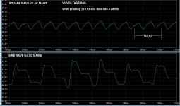
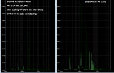
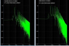
I ran the LT-Spice simulation again, with Square and Sine for 60 Hz AC Mains, and took some recordings of the rail voltage and its FFT, and a rectifier diode's current and its FFT.
This was with a linear PSU with a transformer with 35 VAC RMS output secondaries, wired with no center tap and two rectifier bridges (modeled with 4 MBR20100CT Schottkys each), a 20000 uF 100V cap per rail (each with 0.01 Ohm ESR), and an 8 Ohm resistor load, with a BJT Class AB power amp using one each MJL21193 and MJL21194 with 0.22 Ohms Re, for the outputs. The peak voltage for both the sine and the square "AC Mains" input was 163.91 Volts.
Images are attached. There are significant differences. But I don't think it made any difference in the output FFTs.
Edit: Can't remember if cap was 10000uF or 20000uF when diode current FFT was taken.
Cheers,
Tom
Attachments
Last edited:
This is the Achilles Heel of this approach. If the generated, or regenerated power supply has insufficient current drive, no matter how sophisticated the waveform - in other words the effective output impedance is too great when large current spikes are demanded by the connected device - then the other benefits can be for nought.The Powerplant has different waveforms etc. What these sources do not do is offer different source impedances, something important when looking at the relationships of the power waveform and the power supply. The stiffer the source impedance the higher the current harmonics. Easily 50% harmonic or more. And the current harmonics also present themselves as magnetic fields. . .
There are many reports of this very issue, the "power plants" are fine, so long as they are not asked to feed larger power amplifiers ...
I'm not so confident that a zero source impedance for AC power is a magic answer. The peak power you can draw from an AC line is in excess of 500A (not for long) but if your amp really did this very often the connectors would be a charred ruin on the input and it would suggest something like 5000A on the output. I think the focus on high current sources may actually exacerbate the current field noise pollution I mentioned earlier, possibly adding a sheen of grunge (in sync with the music) over the audio.
Some of the most dramatic improvements on AC power I have experienced were from an exotic filter that reduced the harmonics on the power line and moved the power factor to about .95. It limited the peak current but as long as the supplies held up the improvement was dramatic. Patent US5251120 - Harmonic noise isolation and power factor correction network - Google Patents
Some of the most dramatic improvements on AC power I have experienced were from an exotic filter that reduced the harmonics on the power line and moved the power factor to about .95. It limited the peak current but as long as the supplies held up the improvement was dramatic. Patent US5251120 - Harmonic noise isolation and power factor correction network - Google Patents
Was it Brad Wood or RNMarsh who worked with Monster on their power strips to remove some or most of the ac grunge before it ever gets to the power supply?
Dick Marsh is the high guru of reducing power line noise.
Demian one of my AX articles that is still on their site is a 60 Hz LC power resonator. The circulating currents are quite high. One of the easiest peak voltage improvements. Made a noticeable and measurable improvement.
Demian one of my AX articles that is still on their site is a 60 Hz LC power resonator. The circulating currents are quite high. One of the easiest peak voltage improvements. Made a noticeable and measurable improvement.
Last edited:
Excellent link, Demian - some very interesting material there ... I shall be doing a solid read of it ...Some of the most dramatic improvements on AC power I have experienced were from an exotic filter that reduced the harmonics on the power line and moved the power factor to about .95. It limited the peak current but as long as the supplies held up the improvement was dramatic. Patent US5251120 - Harmonic noise isolation and power factor correction network - Google Patents
- Status
- Not open for further replies.
- Home
- Member Areas
- The Lounge
- John Curl's Blowtorch preamplifier part II