BTW, to address here the jcx concern, there's not a big problem to perfectly match n-ch and p-ch devices (assuming a large enough population is allowed). It is both the Idss, Vp (and hence Gm) and the Ciss, Crss that can't be simultaneously matched. Same applies to power mosfets - matching for transconductance mismatches Ciss and Crss.
Pesky holes and electrons.😀
Waly there are different audiences. I have a friend who stopped writing for amateur radio mags because they had too many articles that "no one would ever build". Because of my background I championed the BF862 and usually poo-poo obsessive matching as a waste of time, but I do like the guys at Linear Systems and would not like to see them go away.
BTW Bob is right about the gm depending on the beta parameter, virtually independent of Idss so that at a given Id the gm is almost the same only going with the geometry (i.e. part type). Try a diff-pair sim forcing Id's the same on two unmatched FET's and take out the offset with a little battery in series with the gates.
Last edited:
BTW Bob is right about the gm depending on the beta parameter, virtually independent of Idss so that at a given Id the gm is almost the same only going with the geometry (i.e. part type).
I believe now it's a misunderstanding in the notations. I was taught that Id=K*(Vgs^2-Vp^2), hence Idss=K/Vp^2. Now if Beta stands in fact for K, then I can agree with you and Bob.
Interdigitation and models
I don't know the folks at LIS, but in my brief exchanges with one some years ago I understood that their duals are interdigitated, an old idea that was publicized many years ago (I can still visualize the cover of one of the trade mags). The person said this should make them lower noise, with which I didn't dissent although thought unlikely. However it should improve the matching, if all else is similar, material quality and process, compared to other duals.
Also, if again I recall correctly, the interdigitated parts in the early days suffered from a low gate-to-gate breakdown voltage. Perhaps LIS has solved this issue.
On the JFET model issue: it seems the major departure from reality for older models is the appropriate treatment of the transition from the low-voltage "triode region" to higher drain-source voltages. I understand there are better models in newer simulation packages that I can't afford at the moment. But for these very-short-channel devices the shortfall is profound. Of course this is another reason to cascode.
Brad
In the "old days" I got NPD5566's for around $1.00 or less so there was no need to look at other alternatives. Why hassle sorting.
Today the story is different. I still have a quantity of the NPD5566's. I use the Interfet parts (a custom variation) for the specialized stuff now. Those are selected pairs from the wafer sorted to my specs. Not cheap but still much cheaper than me sorting parts.
Today the story is different. I still have a quantity of the NPD5566's. I use the Interfet parts (a custom variation) for the specialized stuff now. Those are selected pairs from the wafer sorted to my specs. Not cheap but still much cheaper than me sorting parts.
I believe now it's a misunderstanding in the notations. I was taught that Id=K*(Vgs^2-Vp^2), hence Idss=K/Vp^2. Now if Beta stands in fact for K, then I can agree with you and Bob.
That's right.
On the JFET model issue: it seems the major departure from reality for older models is the appropriate treatment of the transition from the low-voltage "triode region" to higher drain-source voltages. I understand there are better models in newer simulation packages that I can't afford at the moment. But for these very-short-channel devices the shortfall is profound. Of course this is another reason to cascode.
Brad
Virtually all IC JFET inputs are inter-digitated and no it does not improve noise.
Yes, there is a level 3 JFET that AFAIK no free SPICE implementation has, and no manu that I know of extracts these models.
Yes too to jacco's correction of what gets squared.
In the "old days" I got NPD5566's for around $1.00 or less so there was no need to look at other alternatives. Why hassle sorting.
Today the story is different. I still have a quantity of the NPD5566's. I use the Interfet parts (a custom variation) for the specialized stuff now. Those are selected pairs from the wafer sorted to my specs. Not cheap but still much cheaper than me sorting parts.
Aaaahh yes, the wonderful National NPD5564/5566. I used them back in 1982 in my MOSFET power amp. Still have a few around. If I get some time, I may dig them out and see how they compare to something like the LSK389.
Cheers,
Bob
I used the metal can 2N5564-6 in my TAA article of a passive RIAA phono preamp. Well matched. Limited availability, now.
Their noise isnt SOTA now. But about 5nv as I measured -- if memory is still serving me well on this. Very nice device family.
-RNM
Their noise isnt SOTA now. But about 5nv as I measured -- if memory is still serving me well on this. Very nice device family.
-RNM
Last edited:
Here's some data to support my "distortion cancellation with 10% matched n-ch is an illusion" statement.
I took Mr. Cordell's jfet input stage, exactly as depicted in his VinylTrak article, used the NXP BF862 model (parametrized by Idss) and simulated the 2nd harmonic distortions (2HD) as a function of the Idss mismatch. The schematic and the simulation results are attached. In all cases, the 3rd harmonic is much lover than the second, and all other higher harmonics are virtually zero. So the 2HD pretty much defines the THD.
- There is very little relative 2HD frequency dependency in the audio band. I tried 1KHz and 20KHz, and the results are virtually identical.
- 2HD increase very quickly with the Idss mismatch.
- Ideal matching absolute 2HD were 0.25% for 50mV input at both 1KHz and 20KHz and 0.0047% and 0.0066% for 5mV input at 1KHz and 20KHz respectively.
- Taking the 0.9 Idss mismatch as a reference (it's the guaranteed Idss mismatch in the LSK389/489 data sheet) the 50mV 2HD increases by a factor of 2.8, while the 5mV 2HD increases by a factor of 9-10.
Conclusions:
- 2HD cancellation requires very close Idss matching. A 0.9 Idss ratio (as guaranteed by the much sought after monolithic dual jfets) is not good enough.
- Either a minimum 2HD is a critical design requirements (and then much closer matching, perhaps to 1%, is required), or the 2HD is considered low enough, anyway below the audible threshold, and then paying a premium for monolithic duals is useless.
Now, given these results, somebody please explain to a poor EE student why should one pay for the expensive dual monolithic. Modern devices from the same tube (or, even better, dual chip devices, which are always picked from neighbour locations on the wafer) are not far from the dual monolithic devices matching. Also the absolute distortion levels @5mV are already lower than the vinyl plus cartridge distortions, with or without device matching.
Somebody asked about mass production device matching. Set aside this is a DIY forum, if someone needs 10,000,000 matched pairs, I am sure OnSemi or NXP could provide sorting in tighter Idss classes, for a small premium fee per device. 10% matching as for the LSK389/489 would be a very easy task.
BTW, I had to manually match BF862's in 1% Idss for a university project that required very low input offset.
Hi Waly,
There is something seriously wrong with your simulation, and it may not be a correct emulation of my circuit. It is certainly not the full-blown circuit of the MM input stage I use.
The fact that you got 0.25% THD with a 50mV input is a dead giveaway that your simulation is not right.
I went back and simulated my input stage with a 50mV rms input with and without mis-matched Idss on the JFETs.
With matched JFETs, 2nd harmonic was 0.0067%, 3rd was 0.0070%
With un-matched IDSS by 10%, 2nd was 0.0092% and 3rd was 0.0074%
The IDSS mismatch of 10% was achieved by altering the JFET model of one of the JFETs by increasing BETA by 10% (as you know, IDSS = B * Vt^2). If you do this and look at the SPICE error log for the JFET operating points, you will see that the operating gm of the second device is 5% higher, as expected.
Also, make sure that when you use the mismatched JFETs that you re-adjust the input voltage offset to the amplifier to get the output DC level to the same point.
I suggest you simulate the real circuit, with my transistors and my models first as a sanity check, then make appropriate model changes to achieve your desired degree of IDSS match.
It is possible that your models were faulty in some way. In particular, look at the two sets of JFET models you used and take note of the value of BETA in each of those models.
Sanity check everything. The AC closed loop gain, all of the DC operating points, and all of the transistor operating parameters. There is a mistake somewhere.
My results show that a 10% mismatch in IDSS as a result of a 10% mismatch in BETA, and resulting in a 5% mismatch in operating gm, only causes a minor increase in second harmonic.
Until you get your simulation right, your conclusions are suspect.
Cheers,
Bob
I believe now it's a misunderstanding in the notations. I was taught that Id=K*(Vgs^2-Vp^2), hence Idss=K/Vp^2. Now if Beta stands in fact for K, then I can agree with you and Bob.
Hi Waly,
Look at the simple JFET equations on page 2 of my LSK489 App note here;
http://www.linearsystems.com/assets...LSK489_Application_Note_Preliminary_Draft.pdf
This gives the relationships you need. Let me know if you disagree with any of this math.
BETA is an inferred parameter from IDSS and Vt, as BETA = IDSS/(Vt)^2. In real parts with a spread of parameters, but made with the same process and geometry, IDSS and Vt tend to see-saw back and forth so as to keep BETA pretty much the same.
Cheers,
Bob
I used the metal can 2N5564-6 in my TAA article of a passive RIAA phono preamp. Well matched. Limited availability, now.
Their noise isnt SOTA now. But about 5nv as I measured -- if memory is still serving me well on this. Very nice device family.
-RNM
A message worth repeating every so often --
BTW -- the original data from mfr on the device indicated it was a 50nv device. I measured it as 5nV. No wonder no one was using it for low noise circuits. I checked and the most recent mfr data now indicates it is a 5nV device. It was an early life lesson for me was to always measure for yourself before comitting to build a design. Even if your sim's/models are the greatest... the input data must reflect the actual parts being used. Unfortunately, you cant always rely on mfr data/specs.
-RNM
Last edited:
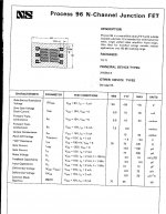
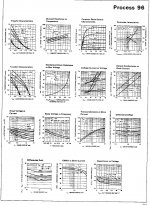
process 96 (5564 et al.)
From an old and very battered National Semiconductor databook, before they stopped showing characteristic curves and then exited the discretes business altogether. Interestingly, this is a dual that has no really close counterpart as a single. The transconductance to input capacitance ratio is very good for those days, and the highish breakdown voltages are handy.
Wonder how big a group buy it would require for NXP to make a dual BF862? Would 100k$ persuade them to pluck adjacent chips off a wafer and package them? 😀 After all, they have a developed process for making two-adjacent-chip bipolars --- one would suppose the equipment wouldn't require a lot of modification.
Having said that, as I don't usually mind judiciously-applied feedback I'm content with singles and less-stringent matching.
Attachments
(Vgs -Vp)2
Yes - each time I'm writing formulas on this forum my brain farts.
If anyone here want to know how audio design engineers understand a part in DETAIL, please look at what bcarso has put up for Process 96. Trust me, I have looked it over, in detail, dozens of times over the decades. You can learn all kinds of things from these graphs. I still use a 2N5564 or Process 96, as a follower to raise the impedance and reduce the cap loading, to make the rest of the Constellation phono stage ideal for MM cartridges.
I'll bet you would need to add another zero to get them to take notice.Wonder how big a group buy it would require for NXP to make a dual BF862? Would 100k$ persuade them to pluck adjacent chips off a wafer and package them? 😀 After all, they have a developed process for making two-adjacent-chip bipolars --- one would suppose the equipment wouldn't require a lot of modification.
There is something seriously wrong with your simulation, and it may not be a correct emulation of my circuit. It is certainly not the full-blown circuit of the MM input stage I use.
The fact that you got 0.25% THD with a 50mV input is a dead giveaway that your simulation is not right.
I went back and simulated my input stage with a 50mV rms input with and without mis-matched Idss on the JFETs.
With matched JFETs, 2nd harmonic was 0.0067%, 3rd was 0.0070%
With un-matched IDSS by 10%, 2nd was 0.0092% and 3rd was 0.0074%
Please post the exact schematic you are using for these results. I used the NXP BF862 model and the stock pspice models for the bipolars. I understand you built this MM pre, what were actually your measured distortion numbers?
Anyway, based on your simulation results, assuming they are 100% correct (which I find highly suspect, only 67ppm distortions at over 1V output swing in the input stage only, I would double check those Early voltages in your bipolar models, I recall from a previous discussion you occasionally overestimated those), the question about using duals is even more stringent. Why spend the money on duals for 25ppm less distortion in a MM pre? Or why not using the dual 2SK3557 available for pennies, for perhaps another 25ppm distortion penalty?
I wish Linear System good luck in the business, although I personally still believe that those expensive duals are boutique parts, belonging to the fashion market (where, BTW, also the "zero feedback" concept lives).
From an old and very battered National Semiconductor databook, before they stopped showing characteristic curves and then exited the discretes business altogether. Interestingly, this is a dual that has no really close counterpart as a single. The transconductance to input capacitance ratio is very good for those days, and the highish breakdown voltages are handy.
Wonder how big a group buy it would require for NXP to make a dual BF862? Would 100k$ persuade them to pluck adjacent chips off a wafer and package them? 😀 After all, they have a developed process for making two-adjacent-chip bipolars --- one would suppose the equipment wouldn't require a lot of modification.
Having said that, as I don't usually mind judiciously-applied feedback I'm content with singles and less-stringent matching.
Why not use an LSK 389 or 489 and be done with it. I just finished up a discrete opamp design and that's what I am going to do. If its cost, ok I understand it, but for these it seems the right way to go.
- Status
- Not open for further replies.
- Home
- Member Areas
- The Lounge
- John Curl's Blowtorch preamplifier part II