This is the world of audio working "properly". Of course the books don't say it's so, therefore it isn't so ... 🙄That reminds me of an enginner who was trying to document very small fractions of a dB changes in my large walk-in microwave anechoic chamber with the chamber doors opened and closed frequently so he could go back and forth to read the instruments racked outside the chamber. The temp variations alone would obliterate any fine data he was looking for. He didnt seem to believe me at first. The temp changes to the microwave cable dimensions alone would affect his readings.
And why the majority of sound systems are sort of OK, but not too brilliant, nothing to write home about ...
Frank
Sy,
If the shapes weren't so organic in nature things would be easier but for a contoured plastic part it gets tricky to do. The only areas that are straightforward are the internal ribs that you could use a 1 1/2 degree cutter to produce and a few holes for core pulls. I'll have to sit down with someone who understands mold design and go over the design. I just hope I don't have to start over, it was not easy to define many of the areas. I started with a wireframe of a few sections and worked from there to produce the surfaces. It was my first time doing anything complex with surfaces like that rather than using the primitives as in solid modeling. I couldn't generate the surfaces that way, they were not definable with the standard arc, line and other tools.
If the shapes weren't so organic in nature things would be easier but for a contoured plastic part it gets tricky to do. The only areas that are straightforward are the internal ribs that you could use a 1 1/2 degree cutter to produce and a few holes for core pulls. I'll have to sit down with someone who understands mold design and go over the design. I just hope I don't have to start over, it was not easy to define many of the areas. I started with a wireframe of a few sections and worked from there to produce the surfaces. It was my first time doing anything complex with surfaces like that rather than using the primitives as in solid modeling. I couldn't generate the surfaces that way, they were not definable with the standard arc, line and other tools.
If I had the funds I would just purchase a small cnc mill and do it myself. I have done things almost as hard on a manual mill, but this hasn't got a straight line on it. 😱
And then there are the tools for the new cone shape. It was easy on a lathe when it was a round cone, but an elliptical shape doesn't work on a lathe.....😡
And then there are the tools for the new cone shape. It was easy on a lathe when it was a round cone, but an elliptical shape doesn't work on a lathe.....😡
No idea. It wasn't there when I tried the same measurement again. I tried a few others from before and got the same results. Except for the noisy one.Ed
What was the source of noise in your previous measurement?
George
If I had the funds I would just purchase a small cnc mill and do it myself. I have done things almost as hard on a manual mill, but this hasn't got a straight line on it. 😱
And then there are the tools for the new cone shape. It was easy on a lathe when it was a round cone, but an elliptical shape doesn't work on a lathe.....😡
Sounds like you might see who in your area wants to demo one for you. Any chance you could write the g code for it?
Small parts in firearms these days are being made with a process called metal injection molding. It starts off like a plastics molding but is converted to all metal in a later step. Some folks swear by it, and others swear at it. A preamp case would be too big, unfortunately.
Thanks,
Chris
Thanks,
Chris
an adapter for PTH would never work well, it uses the copper for heatsink and feedback/sense would just be an absolute bitch, to get close to claimed performance, you would want the reference bypass and FB on the adapter part at which point you may as well do the whole PCB. no adapters but i'm doing a run prototypes shortly.
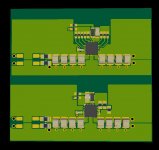
FB is not 100% laid out here in these snaps; i'll be running guarded traces to load point. the missing part at the input is a common mode choke, to form an LRC filter and the bank of resistors on the top reg (the 4700) is the Vout set/div using zero ohm resistors, as well as optional zener elevated 'ground' to hopefully allow running it at higher voltages (thus the prototype). the bottom reg is its negative counterpart, the 3301
the whole bipolar board is ~45 x 45mm
Isn't that device too analytical for toe tapping. I still think you only designed it to trick AD into building you a better phono pre-amp.I like it in that position btw.
New widget from TI
http://www.ti.com/general/docs/lit/getliterature.tsp?genericPartNumber=tps7a4700&fileType=pdf
Would be nice to have an adapter board for TTH.
Attachments
Last edited:
The XP 30 chassis was done by our president Desmond a EE. He also did Krells stuff years ago before Nelson stole him away. My taste is in only in my mouth.
John is correct that the chassis can be difficult I wasn't ever good at that stuff or costing either.
John is correct that the chassis can be difficult I wasn't ever good at that stuff or costing either.
Thanks for being open and straight about it, Wayne. It is still a darn good product entry, and I don't feel 'alone'. '-)
Steve, we generally don't do prints, we submit dxf files.
Same here. I didn't say prints, I said mechanical drawings, which can either be in the form of CAD files or hardcopy prints.
se
Simon,
The local community college has a class teaching MasterCam, if I take that I could probably get on one of the cnc mills they have and do it myself once I debug the code that I am fairly sure that Solidworks is going to cause. I have read enough from others posts in the Solidworks users group to understand that if the entire entity is not one continuous solid without separate sections the cutter paths cause problems when they get to the end of one section and transition into the next section. Believe me I have spent considerable time trying to repair the issue. A few sections come together and have a zero volume section error. Zooming in as much as you can it is hard to find the error and even Solidworks check function has a hard time defining the area that is in question. I've tried all kinds of fixes and patches to connect the sections and have not succeeded to repair the sections. It is very frustrating to say the least but it is a very complex set of sections that were created from surface models that I turned into solids. My other option is to make a set of patterns and have the tooling cast but I don't think I will get the quality I want where the sections have to match perfectly when assembling the three section housing. I could loft the pattern and calculate all the shrinkage but I know I wouldn't get the surface quality that I want for the reflective surfaces when the parts are all done.
Steven
PS. I may just try and do the mechanical mold drawings and use the model to take out the negative space for the core and cavity tooling. I know how to do the tooling, I have designed many molds for my process but they were never this complex for the surfaces needed. I designed the parts to work with the molding method I will use, I know the parts are mold-able and can add all the gating and venting needed and all the core pulls and water lines. The last set of tooling I did for JBL cost them 100K for four tools. I did all the tooling drawings but had a tool shop that is out of business now cut the tools.
Last edited:
A preamp case would be too big, unfortunately.
Not for regular shot molding, but you'd have to manufacture ~100K for the mold to pay off.

Chicken and Egg : whole idea of MiM & sintering is to make it cost-effective.
MiM enables to skip the second stage, taking the fingers off (+levelling the surface)
Plus loss of material, sawn-offs can go back into the melt pool, but the melt has to been cleaned chemically, part of the recycled comes back out as 'yanked skank'.
(also mentioned how expensive an injection mold in that size would be 7 years and 7days ago. extrusion doesn't work, still requires a separate front & back panel, plus extrusion side-lines to machine)
Last edited:
The other issue was capacitor brand. The cheapies had the same results for the first few harmonics but were no where as good at the upper ranges! So now I have to order in samples of all the common brands!
You will find a correlation between the roll method and the upper frequencies. The best is when both leads enter the foil at the same spot of the roll, and it will be the worst if they enter at opposing ends.
When the leads enter at the same spot, the winding of the roll will cause opposing solenoids which cancel. When the leads enter from opposing ends, the solonoid magnetic field is the worst, the ESL highest, and proximity effects will prevent all of the dielectric from carrying current, it is starving the dielectric.
I expect different manufacturers will range from together to as far apart as possible. Low ESL units will of course, be closest.
Same here. I didn't say prints, I said mechanical drawings, which can either be in the form of CAD files or hardcopy prints.
se
Actually, I was only thinking about paper. This computer stuff just baffles me.
That, and G code doesn't seem to support 11 axis motion control.
jn
Investment casting for metal cases, most mil and aero cases done this way.
For complex tools having a positive machined and the tool spark eroded is the way (well the actual manufacturer) I have used for complex parts in the past. Stayed clear of surfaces so far in 3D land, your a braver man than me, but even without surfaces when you start adding features such as fillets and draw angles I have ended up with zero size segments that just wont go away and cause trouble.
For complex tools having a positive machined and the tool spark eroded is the way (well the actual manufacturer) I have used for complex parts in the past. Stayed clear of surfaces so far in 3D land, your a braver man than me, but even without surfaces when you start adding features such as fillets and draw angles I have ended up with zero size segments that just wont go away and cause trouble.
Matce,
I understand completely what you are saying. I didn't have a problem with adding the draft angles and such, I was thinking draft angle minimums and making sure I had no die locks for the parts from the very beginning so that hasn't been a problem. It is the main body sections I had a problem with as I have a very complex design line running through the part which is all curvilinear in all planes and intersects two sections. I get the error that you have seen and I did solve it in a few sections but not everywhere and it is driving me nuts......
jneutron,
11 axis. oh my. Don't believe I have ever seen or heard of that many freedoms of movement on a milling machine. I remember when 6 axis was considered more than enough for most anything. I wouldn't want to have to write the code for that, just keeping track of where you were in relation to the origin would be mind boggling.
It's not a big deal really. Only 8 of the axis are involved in splined interpolation for locked motion, the other 3 are process variable oriented and velocity/acceleration modulated based on the interpolated path. On occasion, I do need to create synthetic 3-D spaces, but only because the degrees of freedom I need do not physically exist. It's only 7500 lines of code, so it's not like it's huge or anything.jneutron,
11 axis. oh my. Don't believe I have ever seen or heard of that many freedoms of movement on a milling machine. I remember when 6 axis was considered more than enough for most anything. I wouldn't want to have to write the code for that, just keeping track of where you were in relation to the origin would be mind boggling.
The most difficult thing is coming back to it after a 2 or 3 year hiatus. I look at the code and wonder who wrote this stuff??? Most of it was written back in '96, so old blocks of code from then, it's almost like seeing it for the first time...If it weren't for my own comments in the code, I'd never believe I wrote the darn stuff..
jn
jneutron,
And what is it that you are creating in this let's just call it 4th dimensional space? What is the end purpose?
And what is it that you are creating in this let's just call it 4th dimensional space? What is the end purpose?
jneutron,
And what is it that you are creating in this let's just call it 4th dimensional space? What is the end purpose?
It's not really more than 3 dimensions. The problem is one of process and vectors. Like a pilot...
Flight NCC1701...what is your location...
Well, I'm right here at x,y,z..
Um, ok flight 1701...where are you going?
Oh, well...I'm goin in x direction at 100 mph, y direction at 100 mph, and z direction at 10 mph.
Ah, ok...so flight 1701, you're going in a straignt line?
Um, well, no. I'm turning towards x at .1 G, towards y at .1G, and I'm laying on the gas and accelerating at 100 mph per minute.
So far, 9 axis to explain where I'm at, where I'm going, and how I'm changing. Imagine being in a dogfight, your target has 9 axis as well, and your bullets retain only 6 once they've been released.. Those topgun guys earn their money.
Change velocity to tool orientation, change accelerations to cutting speeds..
It adds up fast...
My machine welds via ultrasonics, wire onto a b stage epoxy impregnated fiberglass cloth. I take a descriptor file (analogous to a G-code file) and create a coil point by point onto tubes. Kinda like drawing spirals onto a cylinder.
jn
- Status
- Not open for further replies.
- Home
- Member Areas
- The Lounge
- John Curl's Blowtorch preamplifier part II