Seems like these guys gave it the collage try.Look at the topology of the AD797, for a good example.
http://www.diyaudio.com/forums/solid-state/92094-ad797-clone-people-who-can-make-better-one.html
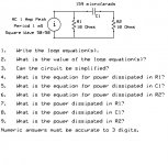
Before I go further let's see if we can get agreement on a really simple circuit.
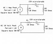
Pavel, Wavey, Scott, SY and anyone else interested, would you each please post an answer to what is the power dissipated in the resistor in the attached circuit?
5W.
Average would be zero? Far as I'm aware, the average of 10 VRMS is 8.99 V.
se
Over half period of sine. Over one complete period it is zero as Ed has stated.
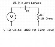
No. 5W for 1kHz/10Vrms sine, 15.9uF capacitor and 10 ohm resistor. Please check the Ed's image, it is really a trivial task.
PMA is a winner.
Impedance modulus of the cap is 10 Ohms at 1kHz, but its vector direction is 90 deg down from 10 Ohms of the resistor active impedance. Total impedance modulus of the RC chain is SQRT(10**2 + 10**2)
From this we calculate current and power dissipated on R.
Impedance modulus of the cap is 10 Ohms at 1kHz, but its vector direction is 90 deg down from 10 Ohms of the resistor active impedance. Total impedance modulus of the RC chain is SQRT(10**2 + 10**2)
From this we calculate current and power dissipated on R.
Dick,
The reason why it is not just Xc/(R+Xc) is the phase shift when R = C is 45 degrees. I do want to go over vector math in a bit.
So who wants to show the Cartesian coordinate system with a 10 ohm resistor and equivalent capacitor value?
The reason why it is not just Xc/(R+Xc) is the phase shift when R = C is 45 degrees. I do want to go over vector math in a bit.
So who wants to show the Cartesian coordinate system with a 10 ohm resistor and equivalent capacitor value?
Ed, please do not. What fascinates me is the lack of basic knowledge even with renowned people. This is really a 'pub threat.
It isn't just that PMA, many of us are 'rusty' and have not done such mental 'manipulation' for many years. When I first started at Ampex in 1967, for example, I was given the task of manipulating Laplace transforms to generate phase compensation circuits for a NASA quality Instrumentation Recorder that operated up to 120ips. Then, I could do it, and it was fun! Today, I can't remember exactly what I did.
It is best not to get too 'smug' as to what it takes to design good analog circuits. This sort of 'engineering' knowledge isn't what is necessary.
It is best not to get too 'smug' as to what it takes to design good analog circuits. This sort of 'engineering' knowledge isn't what is necessary.
When, in late 1989, after the previous business had failed, a recruiter had me interview with Harman. Besides a flock of interrogations with various vice presidents and managers, I had to take a written test. It was based on one administered to FAEs and others at Tektronix. Multiple choice (but show your work), pretty basic, with some discrete components, a tiny bit of Boolean algebra and other logic circuitry. The time limit was 30 minutes.Ed, please do not. What fascinates me is the lack of basic knowledge even with renowned people. This is really a 'pub threat.
I was ushered to the cafeteria, which was initially quiet. Within five minutes it filled with line workers. I soldiered on. The very cold fish of a Human Resources person came to collect the thing at the end of the period. I could already tell that he disliked me intensely after our little chats.
I aced it, one of a couple who got a perfect score. When I went over it with Brad Plunkett, he asked me if I were sure of one of the Boolean questions, and when I said yes I was pretty confident, he marked that answer on the sheet he had 🙂
One of the questions was a cleverly worded one about the voltage at the output of a C-R voltage divider with sinusoidal excitation. Many many people got that wrong, including a VP from Harman-Motive, who wiggled and wriggled to insist that he was right, according to BP.
Vague and poorly worded question, easy to do with a couple of symmetry assumptions (Laplace will work, there's easier ways) once that was teased out of Ed, no real motivation. Time waster if the point of the "exercise" isn't given and the goalposts are likely to be moved.
Well John, I am 57 and might be considered rusty as well. But, my everyday experience dictates me to be able to learn continuously (hw, sw, cad etc.) and not to forget basics. Forgetting basics means one is unable to assess technical/engineering issues properly.
Can't recall that I have Ed. Perhaps tomorrow 🙂Brad,
Have you ever had any engineering use for the average value of a half sine?
Brad,
Have you ever had any engineering use for the average value of a half sine?
Yes, the mean average deviation portion of computing amplifier efficency by class A/B, H, G etc. It's contained as an appendix in my class H ADSL driver paper (ISSCC). It has been referenced in several text books since.
PMA - some of us just don't want to play.
Back to the problem.
Pavel showed a nice simulation and answer that the power dissipation is the same in both resistors. Now for some that doesn't seem reasonable as one is in series with a capacitor and the other is directly across the power source.
So lets look at what happens. As the current starts from zero and rises to one amp the capacitor charges and the voltage across the capacitor rises. This drops the voltage across R2 but since we have a current source the voltage rises across R1.
When the current source goes from 1 amp to -1 amp there is still a charge on the capacitor and this must discharge through R2 so the initial surge current is a bit greater than from just the current source. As the capacitor charges in the other direction we again see more energy into R1.
Now the next issue was can the circuit be simplified? The answer is to treat the current source and R1 as a Thevenin equivalent.
The attached image shows what happens.
For those who don't understand the transform, compare the open circuit voltage and the short circuit current, they remain the same. So the two circuits are equivalents and make it clear that the power in R1 must equal that of R2.
Now that we have discussed power in an RC circuit and reduced the problem to one, What happens if we calculate the power in R2 by using a Fourier series to represent the square wave voltage source?
Attachments
Yes, the mean average deviation portion of computing amplifier efficency by class A/B, H, G etc. It's contained as an appendix in my class H ADSL driver paper (ISSCC). It has been referenced in several text books since.
PMA - some of us just don't want to play.
Wow Scott,
That makes sense on both counts.
SY,
A big part of engineering is defining the problem. If you found it confusing you just could have asked.
Pavel,
I am afraid I will want to do vectors and the unit circle bit as some here don't seem to know it. But I will keep it to one post. You can take a nap then! 🙂
Dave,
I actually expected someone to give the answer of 10 watts as capacitors do not dissipate power. But most of the PM'd answers were 2.5 watts! (And I will not admit to having made the same mistake myself once or twice!)
ES
Yes, the mean average deviation portion of computing amplifier efficency by class A/B, H, G etc. It's contained as an appendix in my class H ADSL driver paper (ISSCC). It has been referenced in several text books since.
Scott, is there a downloadable version?
I found it vague and pointless. Your most recent "problem" even more so: "Solve this using an inappropriate tool."
I found it vague and pointless. Your most recent "problem" even more so: "Solve this using an inappropriate tool."
SY,
The use of loop equations is the first step in analyzing any circuit. Although on a very simple circuit many can isolate the issue and use an easier method of solution, but then when confronted with a large complex circuit having the skills to dissect it and solve it are needed.
Now today most folks will use a simulation program that figures out the loops and does the calculations automatically.
But I think most of us even here recognize understanding how the simulation works even if we could not do the entire job by ourselves is a great benefit.
Now the questions were dead bang simple and what you get out of the answers is for some a refresher, for others a new experience and for some it casts new light on old problems.
You certainly don't have to pay any attention to it. However as you chide John for not doing double blind tests, I reserve the right to chide you for not even attempting the simplest question.
I picked that one because I figured almost every one knows that when the reactance equals the resistance that is the half power point.
ES
Attachments
- Status
- Not open for further replies.
- Home
- Member Areas
- The Lounge
- John Curl's Blowtorch preamplifier part II