Interestingly I was with a customer today talking about oscillators. High volume SOTA oscillators for clocks are at about 0.3ps phase noise with better models offering 0.1ps phase noise. Design of the PLL and associated circuitry is important to get these levels. On board LDO's do the donkey work.
Demian,
If you have some Zout on the supply, wouldn't the oscillator's high speed switching cause appreciable noise on the supply line?
That isn't addressed at all by the Finesse.
jan
The supply only feeds the oscillator!
For clarification, on more closely reading the power supply noise reduction papers linked here, I realize that my superficially similar SHUNT REGULATOR operates on the more primitive principle as a shunt regulator and not by Finessing. The parts count and position are similar, but the two are different in operation. Still, I think that this problem of noise with the LM317 has now been well covered by outside sources and proves that the problem exists outside my imagination. (thank goodness) '-)
Demian,
If you have some Zout on the supply, wouldn't the oscillator's high speed switching cause appreciable noise on the supply line?
That isn't addressed at all by the Finesse.
jan
If your oscillator is switching then your phase noise will go through the roof. A good oscillator is in its linear region always. All of the current demand will be at the oscillator frequency. A cap can do a really good job of supporting that. Getting low Z from an amplifier at 10 MHz or higher doesn't really work.
Jitter specs for Sonet have little to do with audio. The usual jitter spec on a crystal oscillator is for 12 KHz to 20 MHz phase noise. All of the jitter that matters for audio is below 100 KHz and stretches to 100 Hz (AES) or 10Hz or lower (Audiophilia Nervosa). The low frequency phase noise is hard to get low.
OK, I get that. But at a certain point you've got to shape up the oscillator output to a good square wave with very fast risetimes, right?
How do you then supply THAT circuitry to avoid phase noise?
jan
Jan,
Hopefully the Cap Demian mentioned will also do a good job at the harmonics of the oscillator frequency.
I now use mainly SMD oscillators and usually put 10nF 0402 directly at the power connections and 1uF 0603 nearby and some 10uF 1206 close by, but I will use 10uF 0612 in future designs...
The big "canned" oscillators actually have on board decoupling and noise improvements, at least the ones we use.
Ciao T
OK, I get that. But at a certain point you've got to shape up the oscillator output to a good square wave with very fast risetimes, right? How do you then supply THAT circuitry to avoid phase noise?
Hopefully the Cap Demian mentioned will also do a good job at the harmonics of the oscillator frequency.
I now use mainly SMD oscillators and usually put 10nF 0402 directly at the power connections and 1uF 0603 nearby and some 10uF 1206 close by, but I will use 10uF 0612 in future designs...
The big "canned" oscillators actually have on board decoupling and noise improvements, at least the ones we use.
Ciao T
Ballast resistors (or matching) for paralleling JFET’s = A humbug
The calculations are easy to do. Take 2 2SK170’s and parallel them and run them at 10mA total. A matched pair runs at 5mA each for about a total gm of 52.9mS. Now take the two most mismatched possible 2SK170BL’s (6mA Idss and 12mA Idss), the current splits 2.8mA and 7.2mA BUT the net gm is 51.8mS only 2% degradation and only a 1% increase in noise. ANY useful ballasting will degrade the noise much more.
The calculations are easy to do. Take 2 2SK170’s and parallel them and run them at 10mA total. A matched pair runs at 5mA each for about a total gm of 52.9mS. Now take the two most mismatched possible 2SK170BL’s (6mA Idss and 12mA Idss), the current splits 2.8mA and 7.2mA BUT the net gm is 51.8mS only 2% degradation and only a 1% increase in noise. ANY useful ballasting will degrade the noise much more.
Jan,
... but I will use 10uF 0612 in future designs...
Ciao T
horribly piezo - the only way to cram that much C into so little ceramic
large V and T coeffs too
I use the somewhat less bad dielectric 1uF in a ring around my 100 MHz uC - but I have no mechanical vibration to jitter spec to meet
Last edited:
The calculations are easy to do. Take 2 2SK170’s and parallel them and run them at 10mA total. A matched pair runs at 5mA each for about a total gm of 52.9mS. Now take the two most mismatched possible 2SK170BL’s (6mA Idss and 12mA Idss), the current splits 2.8mA and 7.2mA BUT the net gm is 51.8mS only 2% degradation and only a 1% increase in noise. ANY useful ballasting will degrade the noise much more.
Very cool. I'd never even thought to ask. Since gm curvature with Id is so similar among devices of the same type (2SK170, for example) this implies that linearity is also averaged.
Much thanks,
Chris
The sound of one FET clapping
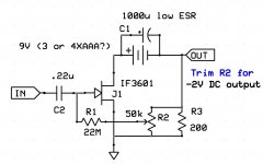
Offered in the spirit of minimalist fun this is about the simplest 20dB front end I could think of. I measured good noise performance (.35nV) with both alkaline and NIMH batteries, though I am told the now outlawed mercury batteries were best in this application. R3 could be split (depending on FET) and the pot could be eliminated. 6 - 2SK170's in parallel should also do the same thing.
Offered in the spirit of minimalist fun this is about the simplest 20dB front end I could think of. I measured good noise performance (.35nV) with both alkaline and NIMH batteries, though I am told the now outlawed mercury batteries were best in this application. R3 could be split (depending on FET) and the pot could be eliminated. 6 - 2SK170's in parallel should also do the same thing.
Attachments
Scott,
The problem is that without a suitable source resistor you will get 18mA current and not 5mA. So to get 5mA Id we need to somehow bias the parallel pair.
And if we work without selection and source resistors the Id may vary from 12mA (2 * 6mA Id) to 24mA (2 * 12mA Id).
Ciao T
The calculations are easy to do. Take 2 2SK170’s and parallel them and run them at 10mA total. A matched pair runs at 5mA each for about a total gm of 52.9mS. Now take the two most mismatched possible 2SK170BL’s (6mA Idss and 12mA Idss), the current splits 2.8mA and 7.2mA BUT the net gm is 51.8mS only 2% degradation and only a 1% increase in noise. ANY useful ballasting will degrade the noise much more.
The problem is that without a suitable source resistor you will get 18mA current and not 5mA. So to get 5mA Id we need to somehow bias the parallel pair.
And if we work without selection and source resistors the Id may vary from 12mA (2 * 6mA Id) to 24mA (2 * 12mA Id).
Ciao T
Scott,
With C2 at 0.22uF I'd rather doubt you even get ten times that value in the low audio band.
Ciao T
Offered in the spirit of minimalist fun this is about the simplest 20dB front end I could think of. I measured good noise performance (.35nV)
With C2 at 0.22uF I'd rather doubt you even get ten times that value in the low audio band.
Ciao T
Scott,
The problem is that without a suitable source resistor you will get 18mA current and not 5mA. So to get 5mA Id we need to somehow bias the parallel pair.
And if we work without selection and source resistors the Id may vary from 12mA (2 * 6mA Id) to 24mA (2 * 12mA Id).
Ciao T
Above circuit is example, works fine with 6X unsorted 2SK170's. (BL's)
Last edited:
Scott,
With C2 at 0.22uF I'd rather doubt you even get ten times that value in the low audio band.
Ciao T
Explain, again above built tested (simulated if that matters), what about a .22uF/22Meg Ohm time constant is unclear? With 10K source as calibration the 12nV noise has no visible low frequency roll-off and the high end rolls off at 6kHz perfectly consistent with ~2.5nF Miller Cgd (this is for 5-40 Ohm MC's). Do I need to post a picture? I could repeat it at work with an instument that goes to DC.
BTW this circuit is 40yr old, it's a FET version of the self biasing bipolar CE stage.
EDIT - Sorry you're talking about noise, The corner was actually around 100Hz that's not an issue I have a bag of 22M from a guitar shop, so put 5 in series. Rememer A weigting is your friend and it's mine too.
Last edited:
Scott,
Nothing is unclear. However, please check your circuit. Most of the audioband will have way more noise than 0.35nV|/Hz, due to your chosen C2 value.
For a very quick estimate I get around 725 Ohm Xc in parallel with 22M as input noise source for a shorted input, this gives me with an equally quick estimate 3.5nV|/ Hz at 1KHz and 11nV|/Hz at 100Hz from this RC circuit.
I understand that you must have adjustable bias to compensate using unselected parts and avoiding source resistors (in production that would be a nightmare, but it is ok for DIY), however your way of implementing this degrades audio noise performance so badly, ballasting / applying a source resistor would be the lesser evil, unless the circuit is intended for RF use only.
Ciao T
Explain, again above built tested (simulated if that matters), what about a .22uF/22Meg Ohm time constant is unclear?
Nothing is unclear. However, please check your circuit. Most of the audioband will have way more noise than 0.35nV|/Hz, due to your chosen C2 value.
For a very quick estimate I get around 725 Ohm Xc in parallel with 22M as input noise source for a shorted input, this gives me with an equally quick estimate 3.5nV|/ Hz at 1KHz and 11nV|/Hz at 100Hz from this RC circuit.
I understand that you must have adjustable bias to compensate using unselected parts and avoiding source resistors (in production that would be a nightmare, but it is ok for DIY), however your way of implementing this degrades audio noise performance so badly, ballasting / applying a source resistor would be the lesser evil, unless the circuit is intended for RF use only.
Ciao T
Scott,
Nothing is unclear. However, please check your circuit. Most of the audioband will have way more noise than 0.35nV|/Hz, due to your chosen C2 value.
For a very quick estimate I get around 725 Ohm Xc in parallel with 22M as input noise source for a shorted input, this gives me with an equally quick estimate 3.5nV|/ Hz at 1KHz and 11nV|/Hz at 100Hz from this RC circuit.
I understand that you must have adjustable bias to compensate using unselected parts and avoiding source resistors (in production that would be a nightmare, but it is ok for DIY), however your way of implementing this degrades audio noise performance so badly, ballasting / applying a source resistor would be the lesser evil, unless the circuit is intended for RF use only.
Ciao T
Professor your maths are sorely lacking. You need to review your parallel to series conversion.
At 20Hz 22me || .22uF = -22e6*36172i/(22e6 - 36172i) or 59.47 - 3.6172e4i. The noise only comes from the real part or about 1nV at 20Hz. I did it in Matlab I did it in SPICE same answer. Also the RC noise goes at 20dB/dec not 10 as you say above.
No need for a larger time constant at the input. Oh, did I mention I built it and put it on a spectrum analyser.
Last edited:
Thorsten is right, bigger input cap, better performance for just about any task.
I see you're still under moderation. The point of diminishing returns is well past here, even .1uF would work fine. This is DIY, with smaller caps folks can still use their exotic materials and spend less money if they want.
- Status
- Not open for further replies.
- Home
- Member Areas
- The Lounge
- John Curl's Blowtorch preamplifier part II