john curl said:Bob, there is a second feedback loop that lowers the drive impedance to the output devices. Also, I would recommend higher Gm parts than you tend to use, so they will bootstrap better.
Hi John,
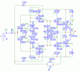
I was apparently looking at the wrong schematic. I was looking at the schematic in post 48 where the MOSFETs are being used. I guess I was supposed to be looking at the JC-3 schematic where the bipolar outputs are shown.
I see the pair of 1 meg feedback resistors from the VAS to the input that you are referring to. Back of the envelope, it looks like these will cause the VAS to have an output impedance of about 500 ohms. This is not as bad as I thought.
If the VAS is feeding four MOSFETs unbuffered (two pairs) and you have Cgs bootstrapping on the order of 14:1 into a 4 ohm load, it looks like the total capacitance of all four MOSFETs that the VAs will see will be on the order of about 960 pF (each MOSFET is contributing about 150 pF from Cgd and 90 pF from bootstrapped Cgs). This will corner with the 500 ohms output impedance of the Vas at about 330 kHz. this open-loop pole will move around quite a bit with signal due to the Cgd variations, but maybe it is far enough out that it will not matter much.
Not sure what the design is running the VAS idle current at, but if it is unbuffered and looking into an average total of nearly 1000 pF in the output stage, it may need to be biased at a standing current of at least 50 mA in order to meet a 100 V/us slew rate.
Cheers,
Bob
Hi Bob,
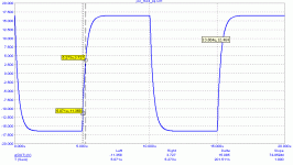
for the simulated bipolar version (post 80), I can see 5V in 76ns, i.e. 66V/us. For the amp supplied at 2 x 25V.
for the simulated bipolar version (post 80), I can see 5V in 76ns, i.e. 66V/us. For the amp supplied at 2 x 25V.
PMA said:Hi Bob,
for the simulated bipolar version (post 80), I can see 5V in 76ns, i.e. 66V/us. For the amp supplied at 2 x 25V.
Oops, I am still not in the SR limited area, BUT exponential rise! The slew rate is really about 100V/us !! - .. it is 125V/us.
Attachments
PMA, 24 ohms for R1, and 20 ohms for R7 might just do it. Also, reduce comp caps to 20pf, then 10pf. Thanks in advance.
Mr Curl,
What happens if your suggestion (20ohm for R7) is splitted to 2x10ohm, each connected to output node? (Q5+Q6'emitors connected to output node, each via 10ohm)
What happens if your suggestion (20ohm for R7) is splitted to 2x10ohm, each connected to output node? (Q5+Q6'emitors connected to output node, each via 10ohm)
john curl said:PMA, 24 ohms for R1, and 20 ohms for R7 might just do it. Also, reduce comp caps to 20pf, then 10pf. Thanks in advance.
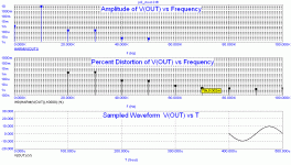
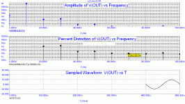
R1 = 24 is fine. R7 = 20 results in high order harmonics to rise, I finished at R7 = 40. Caps of 10pF make stability tricky, it should be at least 15pF, I would vote for 20pF.
Attachments
PMA, you can go back to 20pf or even 30pf. All that I care about is that the open loop bandwidth is 20 KHz or more. The lead cap (2pf) might not be optimum, as well.
40 ohms, with these devices is OK, but I would have thought with a larger device, that the higher current would have been better.
40 ohms, with these devices is OK, but I would have thought with a larger device, that the higher current would have been better.
John, I would finish with compcaps 20pF and FBcap 3.9pF. Please look at square response at 100kHz.
Regardless its age, it is a remarkable design between low-power amplifiers. The speed and distortion spectrum.
I would challenge those who are interested to build it, and fine tune with real-world components. Use polypropylene input cap, no mylar!
Regardless its age, it is a remarkable design between low-power amplifiers. The speed and distortion spectrum.
I would challenge those who are interested to build it, and fine tune with real-world components. Use polypropylene input cap, no mylar!
Attachments
Mr. Curl,
What about R5-R6? If I'm not mistaken, you advised the value should be above 150ohm.
I like the front end alot. Is this applicable to lower biased classAB? Does it have sufficient gain to fix output stage non-linearity?
What about R5-R6? If I'm not mistaken, you advised the value should be above 150ohm.
I like the front end alot. Is this applicable to lower biased classAB? Does it have sufficient gain to fix output stage non-linearity?
R5-R6 is 10 ohms. This is OK. However, R18, R19 could go up to 270 ohms and R1increased to 30 ohms, because of peak current limitation of the BL type.
john curl said:All that I care about is that the open loop bandwidth is 20 KHz or more.
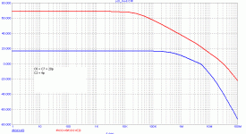
OLG and CLG:
Attachments
i hope everyone is appreciating and enjoying the lessons.
I know i am.
Thanks john and pma!
I know i am.
Thanks john and pma!
PMA said:OLG and CLG:
So am I - thanks again. I think I actually have some of the antedeluvian devices called out for the input stage, but as has been pointed out, the modern alternatives are nicer. If you wanted to match the lower transconductance of the original JFETs, J113s and J175/J176 might work.
What is R10-R11 (10ohm) for? It is in the collectors, and not connected to any other device. Sometime ago I make similiar placement of resistor (on collector of predriver, value 100ohm), it makes Q5-Q6 clips earlier in my amp.
Why is there no cap at all accross VBE multiplier? Usually some 100nf up to some uF is placed accross VBE multiplier.
Why is there no cap at all accross VBE multiplier? Usually some 100nf up to some uF is placed accross VBE multiplier.
For grins, I just did a simulation using J113s and J176s for input devices, D40D7 and D41D7 for cascode transistors, directly driving IRFP240 and IRFP9240 output devices. I used a VGS multiplier to set output bias. Simulated distortion was quite good for such a simple circuit (thanks, JC). Distortion may even be better when I balance out the offset. If anyone is interested, I'll post the circut when I'm finished playing. Fets and cascode transistors were biased fairly hot, which is something I tend to do in any case.
- Home
- Amplifiers
- Solid State
- John Curl amp
