I thought JC recommended not using a coil at the output. Is it really necessary in this amp?
RK
RK
Thanks for your efforts Mike. Nice to see the option to use dual pack jfets - or not.
Mr Curl,
Any comment on the possibility of giving this amp balanced inputs? - or is this not possible with the current topology.
Mr Curl,
Any comment on the possibility of giving this amp balanced inputs? - or is this not possible with the current topology.
Balanced is possible. Mark Levinson did it.
Also, this is an OLD design. The output coil is necessary.
Also, this is an OLD design. The output coil is necessary.
I'm working on it, I'm working on it...
Waiting for some more parts and I'm going to do this PC board optically, as that laser transfer stuff is a nightmare. Initial test runs on a single-ended version have been very promising on the bench. Bandwidth around 160kHz, open loop, with two pairs of outputs. Distortion...um, I think it was about .08% or so, again, open loop. Incidentally, that's with a sub-optimal power supply. I have since switched from the HP power supply to a dedicated one like the one I intend to use in the actual amp.
The new parts are for a slightly different front end, substituting MOSFETs for JFETs in one position. Performance may suffer...or improve. We'll see what happens. That front end will be inherently balanced all the way through, at which point I'll add another rack of outputs on the back end.
Mine is all FET. MikeW's is FETs at the input and bipolars thereafter. His will be easier to build than mine in that bipolar Vbe is far more predictable than FET Vgs when rolling into the folded cascode. In order to accommodate differences in Vgs, I'll almost certainly end up with pots to trim the second stage. A booger, but it's either that or rob a bank to buy enough FETs to match to the precision required.
No, I haven't listened to mine yet.
Grey
Jeez, they really gunked up the ML-2 compared to the JC-2. About a third of that stuff should be removed before even thinking of building one. Another ten or twenty percent could be undone with a little attention to detail. The JC-2 is still there--sorta--it's just covered up.
Grey
Grey
GRollins said:Jeez, they really gunked up the ML-2 compared to the JC-2. About a third of that stuff should be removed before even thinking of building one. Another ten or twenty percent could be undone with a little attention to detail. The JC-2 is still there--sorta--it's just covered up.
Grey
The Colangelo thouch, you mean?
Yes, I once owned ML-2s. Long before I got those I saw the JC-3 schematics in Audio Amateur and started laying out boards. Never finished... Anyway, quite a surprise to see the ML-2 schematics when I got those at last. Of course, there are the regulated PSU also.
RK
The layout looks good. One transistor has the base and emitter labeled wrong. It will be updated. If any one see other changes that need to be made let me know.
I have someone who lays out the boards and does the gerber files. All of his boards have worked. So i don't complain. 😎
John, why doesn't any manufacturer want to build the ML-2 again? Is it not attractive from economic point of view (for the manufacturer)? Is it surpassed in sound quality by the more contemporary designs?
What is in your opinion your most "musical" sounding design so far? Thank you.
Chris
What is in your opinion your most "musical" sounding design so far? Thank you.
Chris
A few questions for Mr. Curl
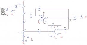
While waiting for my dual FETs I've been thinking on how to servo the JC-3. Only in the simulator for the time being...🙁
Provided that the input FET (J1 in the attachment) is able to drive it, how much can I lower the gain setting resistors of the JC-3 (R4, R5) without getting into serious trouble? I imagine that the two 1M resistors should be lowered as well in order to keep the ratio with R4 constant.
In relation with my first question, I would also like to increase the overall gain to -10. Will the performance be greatly affected?
Thank you for your time and for sharing your design with us!
Attachments
It would be easier to directly sum it into the - input.
A Burr-Brown 134 would be a better choice for a servo. Fet input only, please.
A Burr-Brown 134 would be a better choice for a servo. Fet input only, please.
It might be easiest to use a 2134 to get polarity inversion. 1uF-1meg should be the time constant.
Thanks for your reply,
The sugestions for using a 134 and about the time constant are taken. I was thinking to use this type of servo to 'isolate' the gain equation from preamp output Z, cable L/C...
(some of my friends - 2 actually - have tube preamps and... other home made exotic gear with output Z vs freq unknown. I know I should increase the 15k on the input when visiting the tube guys.)
Even better, add 100 ohm resistor to + input and ground. Then connect 15K (R6) following servo op amp directly to the 100 ohm resistor.
MikeW said:Update. This looks good. I will check it one more time and get some prototype boards.
Hi Mike,
I'm curious as to how the form for your layout came about. Seriously. Is this the way you've layed things out in the past, is there a applications note or book that suggests this, or do you have a heatsink that fits?
The reason I ask is #1 you asked for feedback and # 2 with this layout the most sensitive parts of the design, ie the signal path, are making the longest runs.
If you've had good results I'll say no more and if there is sound logic I'd be interested, as I'm a layout info fanatic (not really, but that sounds dangerous 😉 ). Anyway, I'm actually curious because I see this form factor in many of the design pics posted here and I'm interested mainly because I do things differently.
Regards, Mike.
- Home
- Amplifiers
- Solid State
- John Curl amp