An externally hosted image should be here but it was not working when we last tested it.
That is really a flatish impedance curve. But it still won't like a current amp in the bass. And maybe not even in the HF.
Your clever tricks are really just common sense.
Despite a highish impedance your tube amps (RLD. More?) still have output impedance < speaker impedance so are classified as voltage amps.
dave
Did youI removed the passive high-pass to the mid-bass and rejiggered the cabinet volume to get a B2 as part of the acoustic LR4.
Remove Crossover & Links and Wire Directly External Crossover ?
Yes your speaker has commendably flat impedance in the higher frequencies, but does so by ignoring the place where the biggist common issues are.
"noise" is a placeholder. No marketing happening here that i can see. Just an honest attempt to provide an oft missing piece to allow for playing with current amps.
dave
I don`t see a reason, why there is no such "add" to a speaker crossowers, at least by hi end speaker companies?
This is a bonus for a voltage source amplifiers also. If your speaker impedance, drop from 8 to say 2 ohms at 80Hz , then your imaginary 50W/8Ohm class A amplifier won`t be class A to 50 watts, it will be lot less and so on, that could lead to another set of problems. With "constant" impedance , you avoid that.
"noise" is a placeholder. No marketing happening here that i can see.
Hi Dave.
I am puzzled too. I am not sure what or where the marketing is, it's DIY. It is about sharing. I actually care about DIY very much. I think it is a great cooking pot where ingredients can be chucked and tried. It's also great for those who want to build something - I have taught my three boys that they should work with their hands because their hands are connected to the brain and its development.
The word 'noise' is indeed a placeholder for asking questions. And I consider there are 'primary' questions to be asked.
Just an honest attempt to provide an oft missing piece to allow for playing with current amps.
Well, yes. But that was only part of it. I built the simple Trans-Amp in about a day (and did a bit of tweaking afterwards) in order to prove that the Elsinore Mk5 and Mk6 could be driven by any source impedance and that damping factor was, as Richard Small told me in 1975. just nonsense. One former Hi-Fi shop owner (the shop still exists here in Sydney) had been preaching 'damping factor' for three decades and when I built the amp and since the Elsinore's go very loud with 40 Watts, I played the Joe Morello version of Take Five and it just put an end to the discussion and he never brought it up again. I asked "Where is the damping factor when the amplifier's output impedance is 270 Ohm?" and he was check mated and he knew it and took it with grace.
Re 'noise' - it is at best an interim expression. One of our guys hates the use of it. But there ARE aberrations caused by crossovers. I changed an electrical 3rd order acoustic LR4 crossover in a commercial speaker and the transformation was not due to the amp. It sounded hardly different at all with the Trans-Amp versus another more but high quality amp. The designer was not at all offended (I had told him in advance and had his approval).
So...
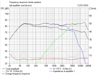
I think there is something significant happening here:
This is voltage driven.
BUT: Now we overlay what happens when driven by a current source:

Does it not strike you, for good or for bad, that we have taken the crossover out of the equation? That is what that overlay graph says.
So, are crossovers audible?
Many would say "yes" without much hesitation. I know they are - and it's not a freq response thing.
I am simply saying that there is something to be learnt here, more than just about current driving.
Also, since both mechanical filters (the alignment) and electrical filters (crossover) can be locked in, their Q remaining unchanged, even when not seeing a zero Ohm source... and yet can be modeled using current compatible software.
Would somebody proffer how that is the case?
It has stumped not a few people down here who should have known the answer (this is Sydney, remember) and slapped their foreheads. It will be figured out for sure.
Finally, current phase angle, is it just the amplifier that is benefiting? If we agree that crossovers are problematic (and that rasies many questions re how) - is not taking the crossover out of the equation a good thing, and possibly cable effects and of course the amplifier itself too.
I am not preaching, I let people decide for themselves, just give me the right as well to draw my own. I am prepared to be wrong, being wrong is also the pre-state for being right. Nobody is born right and we are all taught from the cradle. Questions, questions, questions...
The above have been shown to other (yes, commercial) designers and for free and I never tell them how to design their speakers and they don't tell me. But I believe there are things worth looking at here and they agree.
I keep coming back to the fact that a current amplifier cannot produce anything but current at zero degrees. That this is also good for the speaker? That equalising the impedance is one thing, but equalising the current is really is what is important or as important?
Equalising the impedance allows us to use current, so it does nothing for voltage drive? I somehow think it does.
I think it's good to ask those questions. If something aberrant is happening and we nail it down, maybe we will call it noise, or we may end up calling it something different. If so, using current will reduce the aberration? Then we have a pattern.
But a research project is been undertaken here in Sydney by somebody with significant mathematical clout - raising questions has let to that.
I would love to know what is happening to the the mechanical and electrical Qs above in that overlay graph. There has to be answers.
Last edited:
Very interesting thread, Joe.
I want to get back to how voltage amplifiers really work:
This should be familiar to people who work with op-amps and transistor amplifiers. You have problems with phase, stability and high-frequency loads that force some compromises.
I've built current amplifiers myself, and they just don't like high impedance. Amplifier crossover distortion is a bugbear too. Class A is not easy to implement due to heat issues.
But we need a takeaway from all this. I went on record as saying I thought this Marco_Gea design was very nice indeed.
http://www.diyaudio.com/forums/multi-way/147632-classic-monitor-designs-25.html#post4428857
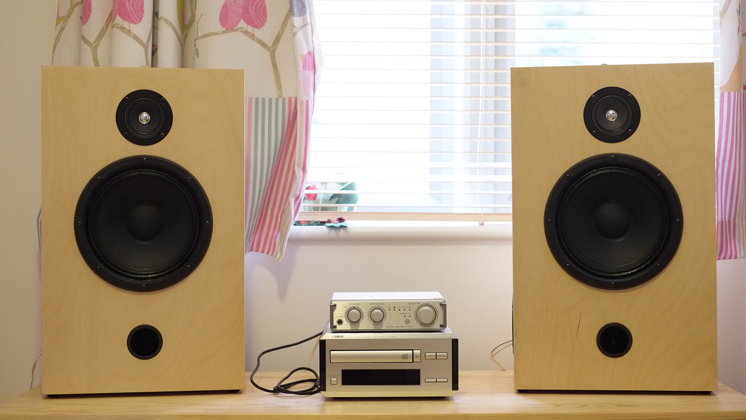
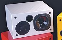
Marco reckoned this 91dB PA bass speaker with a Monacor HT-22 cone tweeter was very nice, particularly at the price. I built something similar myself, just to try out his ideas.
The only criticism I have of it was the slightly mushy and fatigueging or TBH, "harsh" top end. I thought this was due to the lowly second-order filter. But I now know it was the rising impedance on the tweeter. Marco_Gea's filter needs a 7.5R plus 1.5uF Zobel to win a cigar. My own filter needs some shunt resistance, aka an attenuator, on the tweeter. I shall try this, because LR2 can sound extremely good and involving.
I want to get back to how voltage amplifiers really work:
This should be familiar to people who work with op-amps and transistor amplifiers. You have problems with phase, stability and high-frequency loads that force some compromises.
I've built current amplifiers myself, and they just don't like high impedance. Amplifier crossover distortion is a bugbear too. Class A is not easy to implement due to heat issues.
But we need a takeaway from all this. I went on record as saying I thought this Marco_Gea design was very nice indeed.
http://www.diyaudio.com/forums/multi-way/147632-classic-monitor-designs-25.html#post4428857
Marco reckoned this 91dB PA bass speaker with a Monacor HT-22 cone tweeter was very nice, particularly at the price. I built something similar myself, just to try out his ideas.
The only criticism I have of it was the slightly mushy and fatigueging or TBH, "harsh" top end. I thought this was due to the lowly second-order filter. But I now know it was the rising impedance on the tweeter. Marco_Gea's filter needs a 7.5R plus 1.5uF Zobel to win a cigar. My own filter needs some shunt resistance, aka an attenuator, on the tweeter. I shall try this, because LR2 can sound extremely good and involving.
Last edited:
Hi Dave.
I am puzzled too. I am not sure what or where the marketing is, it's DIY.
The questions asked by SY were legit and as far as I'm concerned,
his conclusions were also legit. There is a couple of statements of yours
that are so wrong that it's almost insulting, but as you have already
mentioned, in the spirit of DIY, they have their place under the sun.
The questions asked by SY were legit and as far as I'm concerned...
And a genuine effort has been made to explain.
On the same issue, let's say we have an already lowish design with 4 ohms, then we risk a lower final design like a lower 3/2 ohm impedance, after flattening impedance, maybe not?! Your opinion? Regards.No, there are things that need to work together in just the right way.
The biggest gain is an obvious sense of clarity and resolution.
Ps. Many crossovers have a second option/version for a flatten impedance, is it the same as in your thread? Best.
...we risk a lower final design like a lower 3/2 ohm impedance, after flattening impedance...
Quite so.
Ps. Many crossovers have a second option/version for a flatten impedance, is it the same as in your thread?
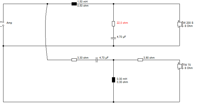
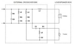
Not quite, if I understand your question correctly. In my approach (philosophy) I make the amplifier see the conjugate part first and directly, and before the component(s) that is the filter. Note that L1 does not have a Zobel.
With the tweeter high-pass, it is a little harder to see that C1, R1 and the tweeter's VC are all in series when in-band. The LC of C2 and L2 are tuned several octaves below and at the tweeter's Fs. So what constitutes the low and high passes elements are all kept in series and things like parallel Zobel are avoided.
I can recommend reading Esa Merilainen's book on Current Driving Loudspeakers and although I suspect he won't see it completely my way (and that's OK, we get on well) he does go into why Zobels should be avoided, keeping all elements in series.
Cheers.
Interesting work Joe! Please, try to avoid red letters on a purple forum background , it`s not pleasing to my eyes 🙂
Interesting work Joe! Please, try to avoid red letters on a purple forum background , it`s not pleasing to my eyes 🙂
Alright, I am sorry, I wear glasses you know. 🙂
Is that colour purple?
Link: Colour Names.
I've been thinking about your ideas today, Joe. As ever, interesting. And we must thank you for sharing them so freely. 😎
I'm a bit muddled here, because I get the feeling you have modified the polycone bass Usher S-520 core crossover to your own taste? 😕
I'm also slightly unconvinced by your notion of speaker voicecoil damping being irrelevant, but clearly you are building the damping into the crossover, which seems valid to me.
I also don't buy your dislike of shunt components. A series filter is nothing but shunt components, and seems Norton-Thevenin equivalent to me!
I've modelled your crossovers before. It's got to be a very well-behaved bass to get away with a single bass coil, hasn't it? Most of them tend to bad cone-breakup with no resistive or RC shunt IMO. Maybe you get away with it with a polycone bass. KEF did in the ancient KEF B110 Cresta.
And TBH, I've had some bad experiences with Fs tweeter notches in the past, especially KEF acoustic butterworth, but see their strengths in a near ideal 12 or 18dB slope.
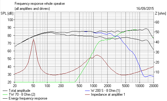
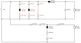
Anyway, here's where I have got to in the (rough and ready) modelling. The dotted line is the fairly benign impedance of the core filter for a 6" paper bass. The solid line is your flattened impedance. Very nice 12dB/octave slope on the tweeter. Flattening a reflex is actaully quite hard, being a double peak, but Joachim Gerhard explained how to do it in one of his interviews.
SpeakerBuilding.com - Interview with Joachim Gerhard of Audio Physic, Page 1
My own feeling is the high frequency impedance flattening is going to be the most audible part. I'd do it with a 7.5R shunt resistor after the tweeter filter, you'd do it with a 8.2R/2.2uF Zobel before. It gets to the same place, IMO.
I'm a bit muddled here, because I get the feeling you have modified the polycone bass Usher S-520 core crossover to your own taste? 😕
I'm also slightly unconvinced by your notion of speaker voicecoil damping being irrelevant, but clearly you are building the damping into the crossover, which seems valid to me.
I also don't buy your dislike of shunt components. A series filter is nothing but shunt components, and seems Norton-Thevenin equivalent to me!
I've modelled your crossovers before. It's got to be a very well-behaved bass to get away with a single bass coil, hasn't it? Most of them tend to bad cone-breakup with no resistive or RC shunt IMO. Maybe you get away with it with a polycone bass. KEF did in the ancient KEF B110 Cresta.
And TBH, I've had some bad experiences with Fs tweeter notches in the past, especially KEF acoustic butterworth, but see their strengths in a near ideal 12 or 18dB slope.
Anyway, here's where I have got to in the (rough and ready) modelling. The dotted line is the fairly benign impedance of the core filter for a 6" paper bass. The solid line is your flattened impedance. Very nice 12dB/octave slope on the tweeter. Flattening a reflex is actaully quite hard, being a double peak, but Joachim Gerhard explained how to do it in one of his interviews.
SpeakerBuilding.com - Interview with Joachim Gerhard of Audio Physic, Page 1
My own feeling is the high frequency impedance flattening is going to be the most audible part. I'd do it with a 7.5R shunt resistor after the tweeter filter, you'd do it with a 8.2R/2.2uF Zobel before. It gets to the same place, IMO.
Attachments
I've been thinking about your ideas today, Joe. As ever, interesting. And we must thank you for sharing them so freely. 😎
Thanks for your kind words. But so far we have really only touched on the tip of the iceberg.
I'm a bit muddled here, because I get the feeling you have modified the polycone bass Usher S-520 core crossover to your own taste? 😕
This and other things you raise shows that we haven't really touched on the philosophy of the crossover and the use of one word, perhaps inadvisably, got things off to a tangent that wasn't helpful.
Let me make this quote, because this is at the heart of it all:
"All might agree that a loudspeaker has to be operated [driven] by an electrical signal. However. immediately next to this, a choice must be made concerning the nature of that electrical signal, that is, whether we seek to control [the] voltage or [the] current of the load, since simultaneously controlling both is impossible [effectively how to steer the driver]. A completely ideal current-drive, as well as a completely ideal voltage drive, cannot be realized, so, in practice, one always has to settle for a compromise that lies somewhere between the two extremes. In which mode the driver eventually operates, is determined by the ratio of impedances of the feeding source and the driver."
Esa Merilainen [Brackets and italics added.]
That last sentence is the crutch of the matter, and Esa and I have basically settled/agreed independently that the ratio should be a minimum 5:1, although I don't see that in print, I came to that ratio myself and asked him and he likewise came up with 5:1 as well.
Dynamic drivers are current devices, it in not the voltage across the terminals, but the current through the Voice Coil that matter, it is what makes the damn thing move.
Note I typed that sentence very carefully and the wording is important.
I want to answer more in detail the things you raise, but what is stated above is at the very heart of it, voltage versus current.
Somebody here invoked Kirchoff's Law, but there are reasons why Kirchoff's Law doesn't quite work and is faced by things that make it fall apart in this instance.
I have a couple of very busy few days ahead, let me get back to you with what might be a somewhat lengthier reply (sorry), but it seems that it is needed. The dynamic properties of a moving coil driver are its own worst enemies and why something beyond KL is needed.
Cheers, Joe
Last edited:
Just quickly, I don't want to leave the impression that KL and TT has no place, it does, it just isn't enough.
Just protecting myself. 😀
Just protecting myself. 😀
Joe, with respect, you continually duck my questions! Perhaps I am overloading you with topics, but I'm really on your side. 😀
I am perfectly well aware that a moving coil loudspeaker is a current driven device. The resistance is only present to stop a voltage amplifier blowing up. Things are less critical with a current amplifier.
My own hobby is getting this 8" paper plus 2" cone closed box baby to sound good. I'm (and I surprise myself...) inclining to 12dB LR2 these days.
I don't know about a pentagonal or "Golden Ratio" 5:1 business. I recall from information theory that a 1:1 source/load matched filter ratio conveys more information. But that's all rather theoretical. 😱
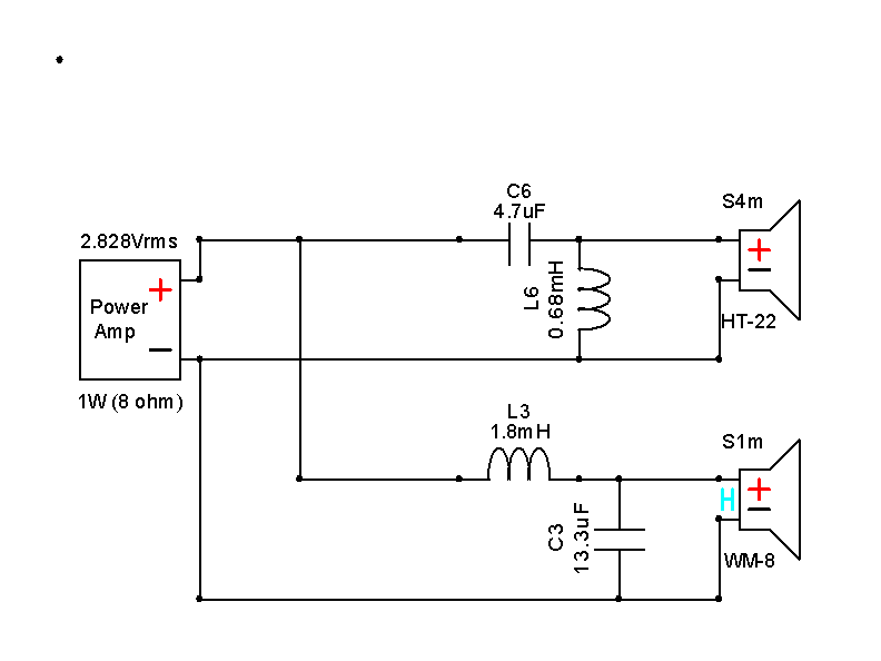
Your CORE FILTER here is quite straightforward:
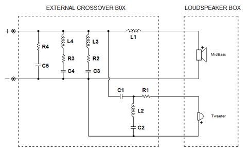
Simple bass coil and second order Fs notched tweeter. 1st order/ 6dB bass and second order/12dB, but maybe 4th order/24dB tweeter acoustically. That has a good pedigree in "sounds good" audio.
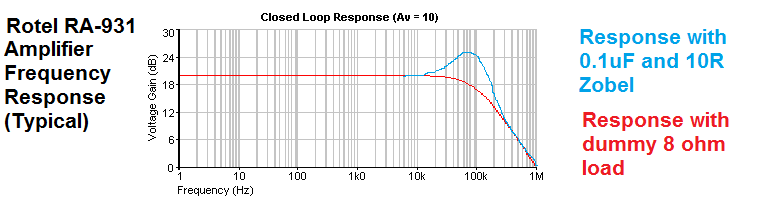
The fly in the ointment is that (voltage) amps don't really behave as a straight wire with gain. In fact they are more like this:
So while I like what you do a great deal, it's the high frequency effects which interest me most. Because the open-loop transistor gain falls dramatically as you get near the top of the band, so voltage feedback doesn't work as well. I suspect that most amps behave as advertised in the bass and 2KHz midrange.
I am perfectly well aware that a moving coil loudspeaker is a current driven device. The resistance is only present to stop a voltage amplifier blowing up. Things are less critical with a current amplifier.
My own hobby is getting this 8" paper plus 2" cone closed box baby to sound good. I'm (and I surprise myself...) inclining to 12dB LR2 these days.
I don't know about a pentagonal or "Golden Ratio" 5:1 business. I recall from information theory that a 1:1 source/load matched filter ratio conveys more information. But that's all rather theoretical. 😱
Your CORE FILTER here is quite straightforward:
Simple bass coil and second order Fs notched tweeter. 1st order/ 6dB bass and second order/12dB, but maybe 4th order/24dB tweeter acoustically. That has a good pedigree in "sounds good" audio.
The fly in the ointment is that (voltage) amps don't really behave as a straight wire with gain. In fact they are more like this:
So while I like what you do a great deal, it's the high frequency effects which interest me most. Because the open-loop transistor gain falls dramatically as you get near the top of the band, so voltage feedback doesn't work as well. I suspect that most amps behave as advertised in the bass and 2KHz midrange.
Last edited:
Joe, with respect, you continually duck my questions! Perhaps I am overloading you with topics, but I'm really on your side. 😀
My previous post could not give the impression of ducking. I have work commitments and said I wanted to give you a more considered response and I will.
Overloading? You have no idea as the answer needs to be about the fruits of much thought over much time. To encapsulate it is not easy, but I will try.
Back asap.
PS: That ratio 5:1 ratio is centre part of it - as you will see.
This sounds like a type remote sensing to me. And topology that was explored back in the 1970's but never really took off. But instead bi-wire caught the wave.
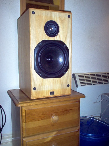
Joe Rasmussen Usher S520 "Current Compatible" Crossover
Subtitled: Can be used with the JR "Trans-Amp" - 40 Watt Transconductance "Current Amplifier"
Link: Trans-Amp on DiyAudio
Last edited:
Somebody here invoked Kirchoff's Law, but there are reasons why Kirchoff's Law doesn't quite work and is faced by things that make it fall apart in this instance.
This I gotta see. Continuity is first principles.
- Status
- Not open for further replies.
- Home
- Loudspeakers
- Multi-Way
- Joe Rasmussen Usher S520 "Current Compatible" Crossover