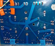
On the other photo (post #311) above, I can't quite see where the ground tracks are running but from the design of the double chip version that Mak sent, the capacitors are where the central, or 'star' ground is located - I would assume your pcb would have a similar ground scheme - so yes, this is your amplifiers central ground point.
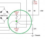
So, as Mark mentioned, if we examine Joe's diagram a little more closely, this central ground point is the equivalent of the green 'dot' between the pair of 4700/50v electros, and this corresponds to the points on the pcb between the power caps (the screw terminals on the edge of the pcb is probably close enough)
This means you have to feed these input power terminals on the pcb directly from the block bridge (ie. remove the external power caps veroboard assembly) by 2 rectified ac
Then you connect your secondary centre tap of the transformer (black wire) to the double ground terminal on the pcb, and from this same point, you run the white wire back to the floating components (the 22R) on the ac input socket's chassis/earth pin.
This will bring you back to Joe's diagram on the post#1.
Something else to consider - that red Wima cap looks like a 1.5uF MKP that is your input cap, yes? If so, I suggest you just extend it's stubby terminals and somehow mount it above the pcb and avoid the off board wires - not sure if it'll fix anything but not good practice (you could position it underneath the pcb if clearance enough
Then, move the input phono plug to where you had the Wima capacitor - keeping the wires as short as possible, including the wires to the speakers, especially the ground return wire that goes 'in' with the other 2 ground wires
You might send a PM to Joe, or Mak, to ask about the problem of 'power down' pulling your speaker 'out of shape' - I would get one of those cheap pcb dc protection kits from china and just use the 'delayed' turn on and 'fast' shutoff feature without any dc protect parts if the simplification of your power supply (and other things) doesn't work
A couple of reference articles to look up, if you would - easy to 'google' them.
Taming the LM3886 Chip Amplifier - Neurochrome Audio article, possibly one of the best sources
Shine7 Audio DIY resources - has links to a lot of other options plus variations on the lm3875 instead of just the '86.
I'm sure it's been mentioned before, but the Mills & Hawkford paper on current drive is worth close reading:
http://www.pearl-hifi.com/06_Lit_Ar..._Malcolm/Distortion_Reduction_with_iDrive.pdf
http://www.pearl-hifi.com/06_Lit_Ar..._Malcolm/Distortion_Reduction_with_iDrive.pdf
R1 = 4K7
R2=33K
R3=22R
R5=470R
R6=10K Trimer
R7=0R33
R8=1K
C1=0.1uf
C2 = 1n5
There is a jumper needs to be set at the back of the PCB and leave out those with JP_GC, JC_GC, I also attached a picture of my built. I am using PD's power supply board from my gaincllone.
Hope this help.
R2=33K
R3=22R
R5=470R
R6=10K Trimer
R7=0R33
R8=1K
C1=0.1uf
C2 = 1n5
There is a jumper needs to be set at the back of the PCB and leave out those with JP_GC, JC_GC, I also attached a picture of my built. I am using PD's power supply board from my gaincllone.
Hope this help.
Attachments
the green circle on the PCB is corresponding to the ground point (greed dot) on Joe's schematic. if you want to use off board DC power supply then just tab into left side of (D2/D4) for V- and Right side of (D1/D3) for V+ and leave out the AC1/AC2 input. Don't forget the GND as well.
Attachments
I did not experience this issue of 'power down' pulling your speaker 'out of shape' , I use the current amp on my MA CHN70.
Syklab,
the photo in post 324 refers to another pcb , different from the one I posted in post 320 ?
kp93300
the photo in post 324 refers to another pcb , different from the one I posted in post 320 ?
kp93300
yes, merged two mono into 1 PCB but the circuit is basically the same. we made just a few for learning eagle. The previous one uses a ground plate in the middle and power plateo n tow sides.
Last edited:
The "Green Dot" is located on the top side of the PCB where 0.33R, power GND and -IN connect together.
Last edited:
As a fellow up, I follow the advice of Mark , JH and redo the power wiring. This improves the hum to low levels that is audible about 10 cm from the 92 db MA12P. I will try shielded input cables and interconnect later.
One thing that is curious is that i have intermittently louder hum that is audible from the listening position,
Mark, I leave the input caps off board for the time being and testing different cap to use.
The sound is very good indeed.
One cannot stop nodding your head and tapping your feet. Music surround you and soundstage is holographic .
I am amazed that it sound so good with so little money!!
thanks to Joe for sharing the circuit.
With that low level of hum, I think you can relegate the problem to 'academic interest' for music listening - has the problem of the 'turn off'/driver excursion also 'gone away'?
I had a stray thought about your intermittent 'hum' problem - it might not actually be in your amp but just maybe be a problem with either the earth connection of your house wiring and/or a household appliance fed from same supply wire from meter box.
I used to do 'pro-audio' and it was quite common to have similar problems like this with the main mixing desk, lighting controls, air conditioners, kitchens, etc at some venues
Hi,
can anyone explain why trim pot left and middle legs are shorted? The way I see it is that amp "in -" sees the same potential as it is on "speaker -" (or 0R33). Unless some internal LM3875 resistance between legs 4 and 8 and parralel dc trim (~10K)+1K create some kind of voltage division..
can anyone explain why trim pot left and middle legs are shorted? The way I see it is that amp "in -" sees the same potential as it is on "speaker -" (or 0R33). Unless some internal LM3875 resistance between legs 4 and 8 and parralel dc trim (~10K)+1K create some kind of voltage division..
LM3886 replacement in the "Trans-Amp"
Hi to all,
this „Trans-Amp“ is a really interresting thing. But i need some help.
Can I use the LM3886 in this schematics too? (because LM1875 is obsolete).
And do I have to do some changes in the schematics to get it working with the LM3886 in this schematics ?? 😕
http://www.customanalogue.com/diy/Trans_Amp_Schema_Wiring_Caution.gif
Hi, can this STA540 little chip be converted to work as Trans-amp? Input/out 1. and 3. would be used. I'd like to use it to drive BetsyK in FAST sistem. 10"bass has some classD amp...
http://www.st.com/content/st_com/en...s/class-ab-audio-power-amplifiers/sta540.html
http://www.st.com/content/st_com/en...s/class-ab-audio-power-amplifiers/sta540.html
Attachments
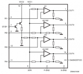
Hi, can this STA540 little chip be converted to work as Trans-amp?
Alas no. Gain is set internally, so not possible as the load has to be inserted in the feedback loop - the voltage gain then changes with load value and that makes it behave as having extreme output impedance of a "current" amplifier. Not possible with your chip choice.
Tnx Joe, I'll see what this little chip can do regular way, but then , I can hear 1875 is calling me... 🙂
Mr Rasmussen, if the LM3875 is obsolete, please, can you re-desing you amp with a actual chip?
While they are no longer manufactured, they were made in such large numbers that they will be readily available for years to come. If I was a manufacturer, then I would have bought well ahead (out my order in) and be well stocked. But I am not a manufacturer.
There will be no problem for DIY'ers getting them on eBay:
1PCS Original LM3875 LM3875TF IC NEW | eBay
Joe, have you looked into the MyRef
My "audiophile" LM3886 approach
My "audiophile" LM3886 approach
And the Modulus-86
Modulus-86: Composite amplifier achieving <0.0004 % THD+N.
Modulus-86: Composite amplifier achieving <0.0004 % THD+N.
I have read a lot about current driven amps before I decided to get these for experiment.
My "audiophile" LM3886 approach
My "audiophile" LM3886 approach
And the Modulus-86
Modulus-86: Composite amplifier achieving <0.0004 % THD+N.
Modulus-86: Composite amplifier achieving <0.0004 % THD+N.
I have read a lot about current driven amps before I decided to get these for experiment.
hajj. you have PM.
James and Mark. thanks for the good suggestions. I will implement changes to the ground.
The other interesting thing is that the hum is intermittent.
I can trim the output dc offset to between 20 to 30 mv ---measure without the load and connected to the pre .
Hi,
Would there be any "spares" still available or is it anyone out there that knows where to get any?
Best regards
/H
- Home
- Amplifiers
- Chip Amps
- Joe Rasmussen "Trans-Amp" - 40 Watt Transconductance "Current Amplifier"