Seems that the video have originate a book, perhaps can serve for made measures best related whit the reality:
Robot Check
Robot Check
Yes, I have come across this video earlier on.
Yes, Raul, if you like his video go ahead and buy this guy's offer and have fun learning... but don't believe him when he tells you that he proved old school wrong and he is the new Nobel prize in EE.
0.33 R current sense
I am accumulating the parts. Joe, can you tell us the type of resistor that you used. Can i use wirewound? Are metalfilm essential? Thanks kp93300
I am accumulating the parts. Joe, can you tell us the type of resistor that you used. Can i use wirewound? Are metalfilm essential? Thanks kp93300
I am accumulating the parts. Joe, can you tell us the type of resistor that you used. Can i use wirewound? Are metalfilm essential? Thanks kp93300
I used 3 x 1R (in parallel = -R333 infinitum) Vishay Dale CW-5, 6.5 Watt resistors, so rated very high wattage in total, more that probably enough. They are high quality wire-wound low inductance resistors, so get something like that and you will be fine. Again, I would get 1R and parallel up three, but if you can get 0R33 that would be OK too, just make it decent wattage.
I used 3 x 1R (in parallel = -R333 infinitum) Vishay Dale CW-5, 6.5 Watt resistors, so rated very high wattage in total, more that probably enough. They are high quality wire-wound low inductance resistors, so get something like that and you will be fine. Again, I would get 1R and parallel up three, but if you can get 0R33 that would be OK too, just make it decent wattage.
Can i use this
35221R0JT - TE CONNECTIVITY / CGS - Surface Mount Chip Resistor, Thick Film, 3522 Series, 1 ohm, 3 W, ± 5%, 250 V, 2512 [6432 Metric] | element14 Malaysia
or this
http://my.element14.com/multicomp/mcknp03sj010ja19/resistor-wirewound-1r-5-3ws/dp/1903863
Last edited:
Parallel three 1 Ohm up of those up should work OK, 9 Watt rating in total. Need six in total.
Hi Joe, I have just built a dead bug version of your amp and is just about to fire it up. Before I do that I want to know if there is a way to protect the amp from releasing magic smoke should the speaker cables are accidentally disconnected from the amp? (I think you have answered a similar question but for the life of me I can't remember where I read it). IIRC, I can put a high wattage power resistor across the output terminals, so the amp sees it as a load?
TIA
Emery
TIA
Emery
In a particular automatization project i looked over the shoulder of designers of car body manufacturing robots where ultra high precision ( less than 0.1 millimeter position error) is a must and they all used current drive of the several motors. That means the motors' mechanical motion is damped electrically, and there is no tedious forth/back/forth...play with sensor data to finally achieve the exact position it is one-shot.
How does a current source amp dampen a motor's mechanical motion electrically? If the robot guys can do it why not speaker guys as a speaker is first of all an electric motor
Btw the effect of impedance around the f resonant of a speaker can be completely and elegantly compensated with a filter in input of the amp which acts as a mirror of the electrical model of the speaker . Not a big thing. The filter usually consists of 3 opamps . It just changes the "transconduction factor" and allows complex values of the factor.
Interesting read is R. Stahl's patent.
Last edited:
Can I use fast blow fuse to protect speaker. Will a 500 ma fuse do for my speaker rated for 30W and a +/- 34 V on the amp ?
If you modify a 'standard' dc protection circuit so just the fast shutoff section on 'power down' disconnects the output relay, that'll do the job okay - could possibly change it to switch the amp's output to a power resistor as a 'standby' or 'mute' option
Why you're getting the problem in the first place needs some further investigation - I'd suggest you look at the raw power supply grounding scheme ...
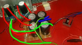
On the early versions of the gain clones, it was found that the power supply caps next to the amp chip were included as the primary ground connection and the raw supply was fed to the amp board using separate ground wires for each '+' and '-' rail (4 wires from raw supply) that also meant that the single bridge and centre tapped secondary winding will possibly need to be altered.
Something else you may want to have a look at, it seems there's a white wire going from the input mains socket to the raw power supply, presumably connected to the black centre tap on the transformer secondary? (It looks like it's connected to the brown '+'ire from the block bridge in the photo)
You may find that if you actually connect this to the 0 volt on the amp's ground point, the amp will behave itself a bit better - possibly 'float' the amp's ground points from the chassis ground via a thermistor, or resistor, cap, diode circuit or other method - often brings improvements ...
Speaker fuse won't be much help to protect the driver from o/p dc offset voltages on amplifier 'shut-down' - just too slow to blow and possibly cause audible sound degradation on transients and/or loud passages with the Alpair 12P driver
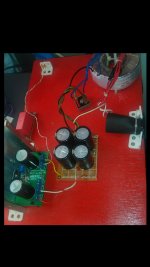
Incidently, where did the pcb come from - it looks to be a specific design for Joe's current o/p circuit?
If nothing else, this maybe food for thought ...
Why you're getting the problem in the first place needs some further investigation - I'd suggest you look at the raw power supply grounding scheme ...
On the early versions of the gain clones, it was found that the power supply caps next to the amp chip were included as the primary ground connection and the raw supply was fed to the amp board using separate ground wires for each '+' and '-' rail (4 wires from raw supply) that also meant that the single bridge and centre tapped secondary winding will possibly need to be altered.
Something else you may want to have a look at, it seems there's a white wire going from the input mains socket to the raw power supply, presumably connected to the black centre tap on the transformer secondary? (It looks like it's connected to the brown '+'ire from the block bridge in the photo)
You may find that if you actually connect this to the 0 volt on the amp's ground point, the amp will behave itself a bit better - possibly 'float' the amp's ground points from the chassis ground via a thermistor, or resistor, cap, diode circuit or other method - often brings improvements ...
Speaker fuse won't be much help to protect the driver from o/p dc offset voltages on amplifier 'shut-down' - just too slow to blow and possibly cause audible sound degradation on transients and/or loud passages with the Alpair 12P driver
Incidently, where did the pcb come from - it looks to be a specific design for Joe's current o/p circuit?
If nothing else, this maybe food for thought ...
James.
The white wire is connected to ac mains ground. the other end is connected to the zero volt line and the transformer centre tap via a 20 R thermistor.
I think I will just place a switch at the amp output to open the speaker circuit before I switch off the ac mains ,
it is rather strange that I also experience a similar hum from another current amp with Lm 1875 !!
the hum occurs even when I short the input pins <
kp93300
Yes. the pcb is specifically designed for Joe circuit. I bought from a fellow member who has some spares.
All over the writings of both the lm3875 and the 3886, there's the same problem of amp 'hum' mentioned and nearly all of it's related to the power supply ground system - with this version of Joe's, you've made it more complicated than his circuit diagram by adding the extra capacitors next to the amp chip and this has created 2 sources of energy for the amp plus 2 separate places for the return power to go to after doing it's job of moving the voice coil, ie the ground of the caps next to the amp, and the ground connected to the raw supply caps - this is why it's clear that the capacitors are actually in the path of the power signal and hence, have a direct effect on the sound of any amp - this one's no different except you have 2, instead of 1.
I suggest you have a look at the Peter Daniels 'gainclone' website for a better explanation on how the ground system for these chip amps is so critical to their behaviour and why Joe has emphasized this in the circuit layout
Now, interestingly, the Brian GT power supply doesn't use the 4 wire method of connecting the power supply to the amps pcb BUT does concentrate all the ground connections on the main ground point on the amp itself - so you don't necessarily need to rebuild the whole raw power supply but possibly just need to alter the way your ground wires are connected -
I think this will solve your 'hum' problem okay but not so sure about the 'shutoff' voltage offset - I vaguely remember the '75 chip is more prone to this than the '86, but not sure what the answer is - pretty sure this has happened before so it probably isn't anything new.
Could you put me in touch of the source of the pcbs if he has some left over? It's certainly neater than my 'dead-bug' assembly.
Oh yes, meant to add - try reducing the caps size next to the amp chips - maybe try some of the 100uF Nichicon BPs (the green ones) or maybe those 'non-electro' ones
Good points made by jameshillj. The ground layout is critical to the amount of hum produced. A 4 wire PSU could work here. A star ground (green dot on schematic post#1) without charging currents passing though it is required.
Also look at where you have connected the input GND. You could connect it directly to the 33k resistor. And, the input wires should be twisted all the way to the PCB.
Did you try measuring the offset? And, how high is it during power down? You can see that the DC-TRIM is connected to the negative rail. At what rail voltages does the speaker cone excursion occur?
Yes. the pcb is specifically designed for Joe circuit. I bought from a fellow member who has some spares.
Would you mind sharing who you bought it from?
I've been eyeing this project for too long, got all the parts needed except a PCB 🙂
Thanks
hajj. you have PM.
James and Mark. thanks for the good suggestions. I will implement changes to the ground.
The other interesting thing is that the hum is intermittent.
I can trim the output dc offset to between 20 to 30 mv ---measure without the load and connected to the pre .
James and Mark. thanks for the good suggestions. I will implement changes to the ground.
The other interesting thing is that the hum is intermittent.
I can trim the output dc offset to between 20 to 30 mv ---measure without the load and connected to the pre .
- Home
- Amplifiers
- Chip Amps
- Joe Rasmussen "Trans-Amp" - 40 Watt Transconductance "Current Amplifier"