Hey,
Really hoping someone can help me out. I have a pair of JM Labs Mini Utopias that have a faulty inductor. Unfortunately it is the only part in the crossover that is not labeled with its value so I have no way of knowing what part to order to replace it. Does anyone have the schematic for the crossover. It is one of the 2 inductors connected to the woofers.
Thanks
Dan
My idea,
If you are not buying an original part from FOCAL, check with them first, what I would do:
0. If the "old" coil is not in good shape anymore...
1. Disconnect the good inductor from the other speaker, "Desolder Components" - How To Desolder Components | Hardware Secrets
2. Take it to a shop or friend w. an inductance meter
3. Measure both inductance and DCR if possible
4. Go to the webpage you need US/EU/Overseas we give here @diyAudio
5. Buy x2 (two) new similar inductors so that you can have a matched pair.
6. Connect and play the music.
I am hard pressed to imagine how your inductor might have 'failed'? Does it have DC continuity and do the soldered joints look good?
JM Labs will surely want to support their products - and would be interested to know of any failure in service for certain.
It will be important with a commercial product of this calibre to replace any faulty parts with the correct component - to ensure it performs as the designer intended.
JM Labs will surely want to support their products - and would be interested to know of any failure in service for certain.
It will be important with a commercial product of this calibre to replace any faulty parts with the correct component - to ensure it performs as the designer intended.
Sorry for the delayed reply. Yes they all have DC continuity and the solders look good. What about a short in the inductor? I don't have an inductance meter. The speakers are more than 10 years old. JM Labs pointed me to their local dealer but they could not identify the problem. They are more of a retailer than a repair shop. Anyone know a good repair shop for speakers in the bay area?
How do you come to the conclusion they (speakers) had, as you say on post#1, ""have a faulty inductor"" ?! Usually they are last thing to break...
It's a pity I can't be of more help. 😉
It's a pity I can't be of more help. 😉
Actually I originally thought that the inductor was losing continuity when I tapped on it with a multimeter attached but now I think that was just fault testing on my behalf. I have contacted the US importer to see if they will service them. It will be expensive to ship them across the country as they are really heavy but they are (were) great speakers so it is probably worth it.
It's almost impossible to destroy an inductor; I'd expect it to be scorched to a blackened crisp before it actually failed. Even then, the most likely failure mode is going open, not a turn-to-turn short.
In other words, if the inductor doesn't show scorched areas, failure is very unlikely. The only exception might be iron-core inductors with small-gauge wire, and a hidden short inside the paper wrapper. In that event, it would be faulty manufacture of some kind.
If the bass driver is silent, measure the DC resistance across the terminals with the crossover disconnected. You should see something between 3 and 6 ohms. If it's zero ohms, the voice-coil (VC) is shorted; if the resistance is infinite, then the VC is open. Either way, the cone (or driver) has to be replaced, since there's no good way of replacing the VC assembly by itself.
If you care about the stereo image, if one driver (or cone) is replaced, you need to replace the driver in the other speaker with a matched driver. Sorry about the expense.
There are defective amplifiers on the market with excessive DC offsets coming out of the terminals; in my book, any amplifier with more than 50 millivolts of DC coming out of the terminals is defective and in need of repair (or re-design).
Last edited:
Hello everybody,It's almost impossible to destroy an inductor; I'd expect it to be scorched to a blackened crisp before it actually failed. Even then, the most likely failure mode is going open, not a turn-to-turn short.
In other words, if the inductor doesn't show scorched areas, failure is very unlikely. The only exception might be iron-core inductors with small-gauge wire, and a hidden short inside the paper wrapper. In that event, it would be faulty manufacture of some kind.
If the bass driver is silent, measure the DC resistance across the terminals with the crossover disconnected. You should see something between 3 and 6 ohms. If it's zero ohms, the voice-coil (VC) is shorted; if the resistance is infinite, then the VC is open. Either way, the cone (or driver) has to be replaced, since there's no good way of replacing the VC assembly by itself.
If you care about the stereo image, if one driver (or cone) is replaced, you need to replace the driver in the other speaker with a matched driver. Sorry about the expense.
There are defective amplifiers on the market with excessive DC offsets coming out of the terminals; in my book, any amplifier with more than 50 millivolts of DC coming out of the terminals is defective and in need of repair (or re-design).
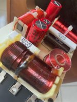
I am new on this forum.... Lynn says it is almost impossible to destroy an inductor but you will find attached a picture of inductor L4 from one of my Chorus 726S. The vernish has melted... JMLab gave my the inductance and DCR of the inductor and I am looking for it but it seems to be difficlut. I will try again using diyAudio: thank you for this!
Attachments
- Home
- Loudspeakers
- Multi-Way
- JM Lab Mini Utopia Inductor