ACD said:6 mA + the Base Current to the output device I would Guess by calculating in my head.......
And in this case what is the current of the BDs?
sajti
My calculation is the following:
The current over R3 is ~6mA, due the output devices are open.But the current over R5 must be ~6mA as well. Because if it less, than the MJE-s are switched off. So I think that the current over the MJEs is equal with the base current of the output devices. Is it OK?
sajti
The current over R3 is ~6mA, due the output devices are open.But the current over R5 must be ~6mA as well. Because if it less, than the MJE-s are switched off. So I think that the current over the MJEs is equal with the base current of the output devices. Is it OK?
sajti
You have to take the BD's into the calculation...
I have never tried this output stage, but the BD's can feed the Bases of the MJL's directly.......
I have never tried this output stage, but the BD's can feed the Bases of the MJL's directly.......
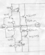
Of course, but not 6 pairs of MJLs for 2ohms... So I think that I will try to reduce R3 and R4 to 22ohm, to get bias for the MJEs.
sajti
sajti
Why ??
Only result would be to drive the driver and predriver harder ??
The total Base Current to 6 MJL's at 100mA idle would be app. 20 mA. That would be total app. 26 mA with R3=100R but 47mA with R3=22R.....
Only result would be to drive the driver and predriver harder ??
The total Base Current to 6 MJL's at 100mA idle would be app. 20 mA. That would be total app. 26 mA with R3=100R but 47mA with R3=22R.....
I plan to use it with valve VAS, so I need triple darlington to get high input impedance.
I have lot of MJE15032/33, but I was not able to select NPN/PNP pairs, because the '33s have much higher B. So I try to find output stage with same polarity driver, and output
sajti
I have lot of MJE15032/33, but I was not able to select NPN/PNP pairs, because the '33s have much higher B. So I try to find output stage with same polarity driver, and output
sajti
ACD said:Why ??
Only result would be to drive the driver and predriver harder ??
The total Base Current to 6 MJL's at 100mA idle would be app. 20 mA. That would be total app. 26 mA with R3=100R but 47mA with R3=22R.....
Yes, but the base current of the output devices is not well defined. And the lower value resistor result faster switch of for the output devices. With 100ohms, and 6 pairs the output stage will be 6 times slower..
sajti
Yes, but the base current of the output devices is not well defined. And the lower value resistor result faster switch of for the output devices. With 100ohms, and 6 pairs the output stage will be 6 times slower..
😕
The Base Current are as well defined as on all other transistors ?
Hfe 25 to 75.....
What do yoy meen by slower ?
No, but the current over the resistor is well defined. I want to define the bias current over the driver.
The charge of the base capacitance of the output devices will be discarged across the base resistor. Lower value base resistor makes the switch of faster. I think You use low value resistor in Your Linx amp...
sajti
The charge of the base capacitance of the output devices will be discarged across the base resistor. Lower value base resistor makes the switch of faster. I think You use low value resistor in Your Linx amp...
sajti
Yes that's right that I use low value resistors in my LYNX Amp 🙂
But not for that reason....
But the MJL's are 4 MHz devices, so they are not slow in the very slow device section
But not for that reason....
But the MJL's are 4 MHz devices, so they are not slow in the very slow device section
Not for that reason, but low value resistor will for switch off too. There will be no cross conduction with high frequency squarewave signal.
The MJLs are 4MHz devices. But if You have to help them to be as fast as they can.
sajti
The MJLs are 4MHz devices. But if You have to help them to be as fast as they can.
sajti
And how will you get a high frequency square wave signal out of your valve VAS to feed into the MJL's ?
😉
😉
The driver use low impedance stages, with direct coupling, and White follower to drive the BJTs
sajti
sajti
Hi, Sajti,
I'm just thinking a simple modification, will it make a better performance?
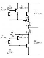
The emitors of BD139/BD140, don't connect them to collectors of MJE15032/MJE15033.
Put new RE from emitors of BD139-BD140 directly to output node (junction of 0.22's). This shifts the function of BD139-BD140 to local CFB output stage.
I'm just thinking a simple modification, will it make a better performance?
The emitors of BD139/BD140, don't connect them to collectors of MJE15032/MJE15033.
Put new RE from emitors of BD139-BD140 directly to output node (junction of 0.22's). This shifts the function of BD139-BD140 to local CFB output stage.
- Status
- Not open for further replies.
- Home
- Amplifiers
- Solid State
- JLH output stage