Greetings everyone...
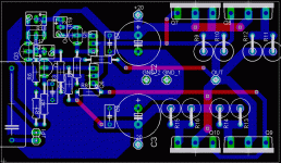
I'm keen on building a pair of (updated) JLH amps to drive the tweeters in my bi-amped system. I've devised a pcb for them, and i'm currently seeking validation and maybe some tips for improving the layout.
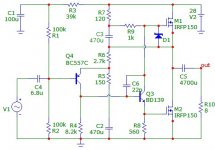
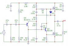
The schematic can be found at this site .
I'm attaching the current layout here.
I'm keen on building a pair of (updated) JLH amps to drive the tweeters in my bi-amped system. I've devised a pcb for them, and i'm currently seeking validation and maybe some tips for improving the layout.
The schematic can be found at this site .
I'm attaching the current layout here.
Attachments
Following some recommendations from that site, i was considering MJL21194's. It's said to oscillate if faster devices are used.
PS: another reason is that i can source some as samples from OnSemi 😀
PS: another reason is that i can source some as samples from OnSemi 😀
I think i stumbled upon that page sometime, but the board is quite big. It says somewhere that the board is 160x100mm. Mine is about 1/4 that size (around 85x50mm), and in don't really have any huge cases available at the moment 

Khron said:Greetings everyone...
I'm keen on building a pair of (updated) JLH amps to drive the tweeters in my bi-amped system. I've devised a pcb for them, and i'm currently seeking validation and maybe some tips for improving the layout.
The schematic can be found at this site .
I'm attaching the current layout here.
Personally, I would move the caps to the other side of the power transistors so that the feedback path is much shorter.
Kind regards
Nico
If you are going to use it for your tweeters only, why need to double up on the power transistors, one pair would be more than adequate for 10 watts or so.
Regards
Nico
Regards
Nico
Now your tweeter amp is class A - which is good. Its phase response is good. I would drop the output to say 5 watt which is more than enough (supply about 15V).
My opinion is that it is not necessary for the extra expense using a center tap transformer here simply because your output cap for the tweeter is relatively small (<10uF/25V).
Furthermore, the PCB has shrunk even more and you may be able to fit it into the small box with "smaller" heat sink🙂
My opinion is that it is not necessary for the extra expense using a center tap transformer here simply because your output cap for the tweeter is relatively small (<10uF/25V).
Furthermore, the PCB has shrunk even more and you may be able to fit it into the small box with "smaller" heat sink🙂
Well.. Frankly, i was thinking of powering them from the same PSU as the woofer amps, and with a high-current regulator (LM317/337 with some solid pass transistors), with +/-20V or something like that.
It's all more or less in the project phase, unfortunately. I've been really busy this year, and didn't spend much time at home, so i couldn't get as much work done as i would've wanted.
I am most grateful for your input, Mr. Ras
It's all more or less in the project phase, unfortunately. I've been really busy this year, and didn't spend much time at home, so i couldn't get as much work done as i would've wanted.
I am most grateful for your input, Mr. Ras

Hi Khron, please drop the Mr. I am only 1000 years old. Personally I think about 5 - 7 watts is good for the tweeter, then you can easily regulate with a single LM337 per each without a pass transistor.
Nico
Nico
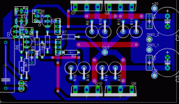
Khron said:I took your advice and moved the caps. I had a bit of work uniting the grounds, but i hope i haven't messed it up more than it was before
Now this is a great looking PCB I like the star on the output, you have the right idea here.
Hmmm.. speaking of reducing power... What component modifications would have to be done in order to reduce Iq ? 😕
(Referring to the schematics in the link in the 1st post)
(Referring to the schematics in the link in the 1st post)
Nico Ras said:
Now this is a great looking PCB I like the star on the output, you have the right idea here.
Final suggestion, run the gnd on the bottom plane and the speaker terminal and track on the top, then your gnd plane is continuous.
Khron said:Hmmm.. speaking of reducing power... What component modifications would have to be done in order to reduce Iq ? 😕
(Referring to the schematics in the link in the 1st post)
Iq should be dependent on the setting of VR2.
Final suggestion, run the gnd on the bottom plane and the speaker terminal and track on the top, then your gnd plane is continuous.
I would, but i did my best to keep it feasible on a single-sided board, and only jumper wires on top (thin or thick, depending on what signal / current they carry).
- Status
- Not open for further replies.
- Home
- Amplifiers
- Solid State
- JLH amp pcb


