It can work, but your approach is certainly better. It would be an interesting amp to make, I have some of those old hitachis🙂
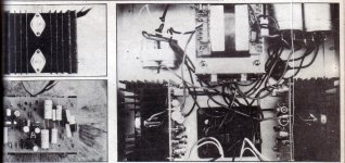
It would need the gate stoppers direct on their pins at least, surely they knew less on that construction (1984), but it apparently worked as depicted. They even tested their build as 100W on 8 Ohm 20Hz 0.01% 200Hz 0.004% 1kHz 0.003% 10kHz 0.02% 20kHz 0.025%. Maybe it could have measured better if they had D.Self's advice on wiring that became known later. The builder/reviewer had a Systemdeck with Linn basic LVX arm, Grado GF1+ cart, Naim-Nac 32, BBC LS35/A and DIY B139 ported sub with passive cross. His comments were it was neutral with obviously smoother mid-highs than BJT amps he had tested (probably vs NAP-250). He also found the bass taut and strong, noticing it improved there with bigger reservoir caps.
Attachments
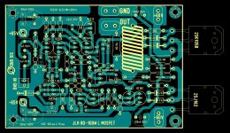
PCB option
.....I have layout PCB for 2SK1058 and 2SJ162 output transistors in 6hours 🙂
it's first try , but I can do better then this .
Regards Alex mm.
.....I have layout PCB for 2SK1058 and 2SJ162 output transistors in 6hours 🙂
it's first try , but I can do better then this .
Regards Alex mm.
Attachments
Last edited:
Ah! This is very nice of you Alex. Now you really breathe second life to the child of the respected designer, a homage since he is no longer in life. Bravo.
P.S. It does not trip bias with BC182 off heatsink on mine by the way, seems that the 100mA 0TC bias worked nicely with the 135/50.
P.S. It does not trip bias with BC182 off heatsink on mine by the way, seems that the 100mA 0TC bias worked nicely with the 135/50.
JLH was giving +/-80V max with just one pair K135/J50 for 160W 8 Ohm. So with 2 pairs it can be 4 Ohm rated I suppose. Does anybody see any drive deficiency from the CCSed VAS? Looks like 7mA running in the 200V Vceo driver. Mini-sinks for the MPSAs likely needed if with higher PSU.
I don't recall reading of a JLH Class AB Lateral mosFET amplifier with this spec.JLH was giving +/-80V max with just one pair K135/J50 for 160W 8 Ohm.
Can you refer us to model or article or other source?
...Another thing, shouldn't be the gate stoppers go half value when with two pairs to preserve the same OLG frequency characteristic?
Although acceptable by the late 70s standards , this amp is no more
a recomendable one , and the only good thing is the presence of the
famed 2J50/2SK135 pair...😉
Indeed, using only a pair of these laterals for such high power
is indicative of the early technology it still was in 1982, and as such,
was still not very well understood.
At least two, or better, three lateral pairs is a minimum for +-50V PS
and anything below this quantity is just plainly not enough..
The 680R gate stopper are way too high, 100R is a maximum
value with these devices, and if the amp oscillate with such
values, then it s simply not designed accurately.
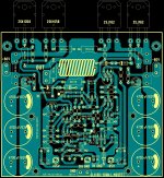
A modern simulation of its behavior with the doubled up plastic laterals as in the second pcb approach, could indicate possible oscillations, value changes in the compensation, or VAS BJT type changes for the better PM, THD20, IMD, etc.
I simulated it extensively , and i ll post the datas in some times.
Whatever i tried to improve it was not successful, wich led me to think
that the whole thing was to be reconsidered, and better, abandonned..
When i get some time , i ll also post some findings about the best
way to use Hitachi s laterals wich are truly a breakthrough in audio components.
Too bad their devellopement was halted long ago along with the production
of TO3 variants.
It will be very nice to see how it behaves on the simulator for OLG, PM, THD, IMD. Please post Spice screens when able. Back then JLH could not have such tools, but he surely had a stable working low offset amp on his bench, before publishing it. Mine never blew, I had used it loud on 4 Ohm etc.
A few pictures in the waiting of a little more...
Attachments
Nice to see, thanks! But can you add the missing filters and rerun? The amp won't go that high closed loop, it has 1nF to ground after the 4k7, I remember its 10kHz square wave a bit rounded on my scope. Without it oscillates. I have tried it. It also misses the series R//L Zobel on output in the sim. I had a reduction from 0.20% to 0.00125% for 1kHz 1W when I restored the Zobel.
1nF & 4k7 gives 4.7us RF and Audio filter.
How low can this go and still stay free of oscillation? 330p, 220p, 150pF?
As far as I can recall JLH usually used the full Thiele Network on the output.
How low can this go and still stay free of oscillation? 330p, 220p, 150pF?
As far as I can recall JLH usually used the full Thiele Network on the output.
Nice to see, thanks! But can you add the missing filters and rerun? The amp won't go that high closed loop, it has 1nF to ground after the 4k7, I remember its 10kHz square wave a bit rounded on my scope. Without it oscillates. I have tried it. It also misses the series R//L Zobel on output in the sim. I had a reduction from 0.20% to 0.00125% for 1kHz 1W when I restored the Zobel.
Bandwith and phase response must be computed without input
and output filters to give an idea of the amp s caracteristics.
With the filters connected, the picture is made way more rosy,
although adding a zobel network will not change the THD ratios,
moreover at frequencies as low as 1KHZ.
Attachments
Hi Andrew,
I don't think JLH did ever use a "full Thiele" net work. That's if we're discussing the same thing. As I understand it the first network was an LR in series with speaker and then a simple cap from the output (i.e. the speaker end of the LR) to ground. The speaker went across the cap and you ended up with a stabilizing network and an first order RF filter. Cherry discusses this in one of the two articles in Wireless World called "Ironing out distortion". (mid 90's I think)
Quite by chance, while looking up some other stuff, I found the original paper in the JAES where Thiele first published this family of networks. The one Cherry talks about and the one that was seen in a magazine diy amp' here in Oz in the late 70's are first order configuration. In the JAES paper he has additional second and third order networks for really bad cases of RFI! Never seen anything remotely like it anywhere else and obviously half a dozen caps, resistors and inductors......in one there was bifilar winding for the feedback take off point.......can't recall exact circuit configuration....
But it will turn up when we move house in August and I'll send you a copy if your interested.
Cheers, Jonathan
Last edited:
- Status
- Not open for further replies.
- Home
- Amplifiers
- Solid State
- JLH 100W L-MOS 2nd Life