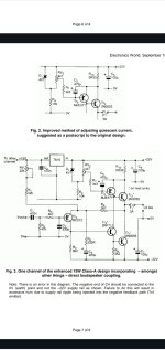
That's similar to what I did in my design, see attached.This is what I'm thinking. Look at this image. The amp output is set to 20 volts DC here and appears 1 second in. The output side of the cap is charging via a 100 ohm here and after a few seconds the voltage has fallen to a very low value.
(Don't pay much attention to component's values and the fact that NPN device is drawn in "anti-pop" circuit. I am just too lazy to fix the schematic).
The idea is simple: during startup amp's output is connected to 10 Ohm resistor, after ~1 second after power up relay switches output to speakers.
The relay circuit has dedicated rectifier and very small bypass cap so that power off it switches off the speakers faster than main amplifier supply is gone.
I've tested this part and it works fine, however I'm not sure if timings are ok. Perhaps it will need some adjustments later.
Attachments

Interesting. Positive earth. You could try a P channel FET for the relay driver and use a much smaller timing cap and higher value charging resistor. That would also allow much more of the exponential charge curve to be used before the FET conducts.
😎
😎
Yes, apparently that was quite common for old germanium amps.Interesting. Positive earth.
Well, here the point was to use germanium only 😀You could try a P channel FET
Yes it was very common for what was mainly PNP output stage based circuitry. If you are using Germanium for the relay drive then the 'problem' of using hardly any of the charge curve is even more pronounced.
What I would do differently...
The transistor will start to turn on at around 150mv base voltage so that is all the 100uF cap will really see. If you added a Zener in series with R11 and a resistor across B/E you could use much more of the 'curve'. I would also look at scaling the resistors up as it will consume quite a bit of current as it is. With a 24 volt relay the 24 volt Zener shouldn't be needed. You can always add a bit of resistance to the relay coil if needed.
🙂
R9, R4 basically is a voltage divider which makes it ok to have C10 charge only to ~150mV 🙂The transistor will start to turn on at around 150mv base voltage so that is all the 100uF cap will really see. If you added a Zener in series with R11 and a resistor across B/E you could use much more of the 'curve'.
Oh yes, of course. As I mentioned, the values on schematic are completely wrong.I would also look at scaling the resistors up as it will consume quite a bit of current as it is.
Do not agree here. In case of fast ramp on C6 and while voltage on C10 is still ramping up - Q4 can get >30V on Vce and Vce max for the device I use is only 30V. So the zener here is to protect Q4, not to regulate voltage on the relay.With a 24 volt relay the 24 volt Zener shouldn't be needed.
Hello…I have a question. I’m thinking of building a jlh. I have the transformer already. 2x18v 500vac. I am going to use it for a near field application in a small space. Gonna be using 3-1/12 speakers for midrange and add a small woofer for low. My question is which schematic should I use for it. The 1996? Or the original? I am looking at the Geoff schematic. I don’t need a 25 watt class an amp so I was thinking the original. Or would biasing the amp at say 1 amp be ok for it? TIA
An 18 v ac winding will get you around 6 watts into 8 ohm @ 1 amp bias current before clipping. The original JLH69 (imo) would be the one to go for... its a classic.
Personally I would stick with the original design and concept. The later design (imo) does not really lend itself to split rail dc coupling as shown and once you get onto split rail and regulated/stabilised supplies you are moving to a different level of heat dissipation and thermal management.
Yeah, the extra benefit with the original circuit is that you dont need spkr protection, just a delay circuit is what you want.
A dealy circuit that temporarily disconnect spkr from amplifier output to eliminate turn on off pop.
Hi all, bit of a tangent,
1996 version, trimpots RV1 (22K) and RV2 (4k7). I've read in a couple of locations about power rating requirement issues and the fact that commonly available trimpots are only, typically, 0.5w.
Using ohms law for voltage drop and resistance the power dissapation seem very low, so thought to double check with you guys why the general concern elsewhere.
Other than size, I've seen these which should be 'adequate' at a rating of 2w.
Attachments
Good lord, totally overkill! Notice the little blue things in the far back. This thing has been running with them for I cannot even recall.

Thanks Nico, 👍, those trimpots are 0.5W which is more than comfortable using my dissapation calcs.
Nothing wrong with over rating though! One good thing about those is that I could mount them on the case to manually adjust dc offset and Iq if there is any drift.
That is a nice build, funny engineering, encase heatsink with wood and stick a fan on the end 👌
Nothing wrong with over rating though! One good thing about those is that I could mount them on the case to manually adjust dc offset and Iq if there is any drift.
That is a nice build, funny engineering, encase heatsink with wood and stick a fan on the end 👌
It was to make a funnel or chimney. Just blowing air was not enough it got ******** hot to touch. Class A is another animal if you are used to class AB. At 10 + 10 watt you looking at more than 80 watt heat dissipation. That little heat sink was just not enough to stop it burning me without forcing a little wind through it. 🤣 BTW once when you set the bias, you will never set it again. Set it during start and then trim it after an hour or so, it is done.
Last edited:
- Home
- Amplifiers
- Solid State
- JLH 10 Watt class A amplifier