The problem with BD139 is knowing if it's a good spec version.
I have concerns too about the BD139, but devices from On Semi and ST have measured as being high frequency. My concern is that the fT line is missing from both ON Semi's and ST's datasheets
Yeah, I noticed that too. Curious omission. The 139's are ST, just recv'd from Digikey, no mention (or choice) of grade. I haven't tested them yet. I also got a few ZTX450 (Diodes Inc) to check out. Their Hfe is very inconsistent.
Digi also sent me some 200V 'lytics (for another project) with 2012 date codes. ESR measured above 10 Ohms on all of them!
It's a fun little exercise to invent and build a fixture that lets you measure fT in your own workshop.
That would be a good learning exercise. Can Tek 577's do Ft? I have a couple (sans fixtures) waiting for 15+ years for me to repair.
Last edited:
Ah! the good old Tek 577. That is just a curve tracer as far as I recall. Good for characteristics but don't remember it being able to measure ft.
You only need an RF signal and an oscilloscope as a basic setup for ft measurement. (perhaps you can add parts to use the CRT as an oscilloscope while you repair it?)
(I've got a few ST and ON semi BD139/Bd140's, not had a problem with them BTW. As long as they are from known source should be OK).
(Surprised about the ZTX 450 gains. But don't know where they are made these days since Ferranti/Zetex sold out).
Last edited:

That configuration in the post above suffers latch-up on overload.
Needs optimising.
Surprised about the ZTX 450 gains
Management Team
Keh-Shew Lu
Chairman, President, and Chief Executive Officer
Member, Risk Oversight Committee
Francis Tang
Senior Vice President, Worldwide Discrete Products
Emily Yang
Senior Vice President, Worldwide Sales and Marketing
Evan Yu
Senior Vice President, Worldwide Power Products
Gary Yu
Senior Vice President, Business Groups
Jin Zhao
Vice President, Worldwide Analog Products
To be clear - the circuit which I referred to as latching up is the one with the modification I mentioned in #7889. Not the one OldDIY has posted.
And the previous circuit which I mentioned (using the current mirror and increased PNP current) does not.
And the previous circuit which I mentioned (using the current mirror and increased PNP current) does not.
No one teems to have noticed this. An overstocked CRT driver I would guess.
ON Semi KSC2383YTA NPN Transistor, 1 A, 160 V, 3-Pin TO-92 | RS Components
Some of the amplifiers that sounded most distorted were the ones with least distortion. Quad 405 being one ( not the worse by a mile ). Not just it's current limiting. It was musical wallpaper. I had to use the 405 and could make it sound reasonable. The Hitachi MOSFEET design of that period had exceptionally good distortion figures yet sounded more like a top grade tube design. 7 active devices of which 2SD756 was like the KSC2383Y. Y is high gain. It's not the distortion, it's how you got it.
If you make yourself believe a Quad 405 represents real music you will find music in a concert hall highly coloured. Beethoven sounds like 78s. When it does that's heaven for me. Oxfords Sheldonian ideal to hear this. Mahler played on the same night colder and more transistor like. Beethoven has massive jazz like elements to require tight bass. It's easier to judge classical.
Have you ever listened to live music and found yourself thinking it is hi fi? I have. Mostly that stereo is complex and seldom real. Good mono can be better as long as two speakers used. Fake mono is no way to tell. However, mono made from stereo that sounds good likely is good stereo.
Some of the amplifiers that sounded most distorted were the ones with least distortion.
It's not the distortion, it's how you got it.
There are many kinds of distortion. It just cannot be represented by the THD.
My tube amp had no negative feedback except one tube was a near Triode. No un-bypasssed cathode resistor to get the gain I required. This was done using a Penode in anti-phase. After much testing I found any Pentode of the type worked as I wasn't at maximum current ( 30 % ). I had about 30 samples from many source's. Some considered dead. The idea is what I call East-West Ultra Linear. I used a little North-South type as in Hafler patent on the near Triode. One can use a speaker secondary to do that in the EL34 cathode as PYE Mozart. That is Peter Walker UL. A small DC current in the speaker is a factor when PYE style. I did some testing at the old PYE labs in the distant past ( I talked to them recently as I might restart that project ). Good fiends of mine if they remember me. They have military type facilities.
The triode is at the output to get a lower impedance. I tried feedback on it. The magic was lost. 0.2 to 1 % THD is fine. If you don't think so it's likely a secondary reason. A ghost in the machine.
The distortion at 1 watt very like my PAM4603 amplifier I use for TV.
The 6 watt amplifier I describe has a low damping factor so won't suit every speaker. It was best using Quad ESL63 and was loud and very undistorted. Far better than a 405.
The only reason I say this is knowing something is knowing all variations of an idea.
Member
Joined 2009
Paid Member
#7885 save a dying patient before putting it down - From a local forum: Simulators suggested using an inverted phase splitter stage. Just install PNP BD140 in place of BD139 (emitter up, collector down).
In front of it, add the usual cascade of the OE npn (emitter to ground, base to collector T1, collector to base BD140 and 10 kΩ to (+). It is said that distortions are reduced by an order of magnitude.
You may have to pick up resistors in the feedback and correction.
That sounds most familiar! In fact, this is also known as the “JLH Follower” (unity gain) circuit. It’s very good and not used often enough.

The lower resistor collector load T1 and the base current of the lower BJT transistor (Like 1969).
The upper resistors set the base current of the lower transistor (and the upper one in the other half-cycle). A current source is recommended.
Balancing the resistors is recommended when using mosfet.
Last edited:
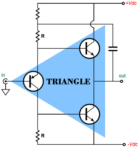
Улучшенный выходной каскад УМЗЧ на полевых транзисторах — Меандр — занимательная электроникаIn Tubeсad's Triangle R=R.
In Nikitin's follower R1=10R2.
Why?

In Nikitin's circuits with BJT, the phase splitter is current-loaded with a low input resistance of the output transistors (Less than 50 ohm). The resistance of the lower resistor provides the turn-off speed of the lower output transistor. Symmetry is affected from 500 ohms. Eliot uses the 100 ohm resistors in DOZ.
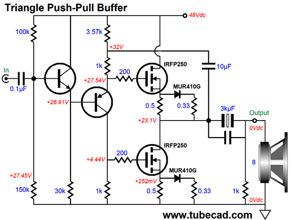
In Mosfet or Darlington circuits, symmetry is achieved using gate-drain resistors. There may be a transition from a push-pull class AB or A to a SE dynamic load mode.
This was shown by Millwood at the beginning of the branch.
Last edited:
An externally hosted image should be here but it was not working when we last tested it.
Opamp NE5532
Returning to 1969 JLH. I see the input impedance of the driver phase splitter as being the source of IM distortion in this and many designs. JLH seems to make it pure transconductance between input transistor and driver splitter. As Zin relates to hfe times re, we make re and hfe as high as we dare. I chose BC337-40 for this reason.
I would image the Cgd aand Cgs of FET's to be higher than bipolar devices impediments ( 2SC5200, Cob etc). I imagine JLH is marginal even with the bipolar options.
I built a complementary feedback pair with compensation capacitor. It did everything I wanted except sound good. It was as a VAS. I never tried a cascode in transistors. With ECC82 or 12BH7A I have and found them a little bit wonderful. The great beauty of the JLH is it is the missing link between tube and modern transistor designs.
Quad 50E - The phase splitter is formed by a discrete Darlington transistor Tr2-3 (2xBC109). Coupling through blocking capacitors. Low AC voltage.
Output transformer. The arms of the output stage have the same elements.
Choke in power supply. The preamplifier is powered by a linear regulator.
Quad 50E circuit diagram - large copy
Output transformer. The arms of the output stage have the same elements.
Choke in power supply. The preamplifier is powered by a linear regulator.
Quad 50E circuit diagram - large copy
Last edited:
- Home
- Amplifiers
- Solid State
- JLH 10 Watt class A amplifier