personally I buy wrecks of grundig sv40 and also sv85, for two reasons, the power transformer is a 2x16 Vac of very good quality and with screen and also because it is filled with extraordinary philip transistors that I can recycle at will on other Naim and nytech devices
Last edited:
Replying to several of the above posts regarding the beefy transformers. I might use the parallel o/p transistor version as per the 'Class A website' The Class-A Amplifier Site - JLH Class-A Update. To dissipate the heat. I'm also considering a 4 channel amp. These are my speakers. Full Range Speaker Photo Gallery. A woofer assisted wide-band with 1st order crossover.
However I might go class AB chip amp for the woofers but use the same PSUs.
However I might go class AB chip amp for the woofers but use the same PSUs.
400 VA will sound better due to it being the better time constant with the capacitors. Many amps have too many uF and not enough copper. My little NAD 3020 sounds better with smaller capacitors. Less boomy. I only have the NAD as a work horse. I really like it if wondering. Naim amps only have big transformers as the upgrade up to the NAP 250. They sound very different due to that. JLH being class A might not show this. In a way class A is a very bad type of amplifier except voices souund great. My hunch is it still is best with 400 VA.
That's still a lot more transformer than warranted when the standing current requirement is only 1.2A with a single 27V rail. I don't suggest anyone use a transformer for class A amplifier duty that sits right on its maximum rating but you're suggesting transformers with capacity more than 10 times that, which I think is well over the top and rather heavy for a modest 10W stereo amplifier.
With the NAD 3020 Nigel, I think you picked one of the world's stingiest amplifier designs for power supplies (and other things too). Users are even required to switch down the transformer windings to allow the safe use of 4 ohm speakers. What's more, the transformers are also prone to get warm, loosen up and buzz away annoyingly, sometimes to the beat of your rock music. 'Small wonder that a larger transformer would make that model sound a lot better - probably any decent transformer would too.
The significant difference with NAP 250, is that along with the NAP135 mono versions, they are the only models with a regulated power supply and consequently, more iron. If regulation doesn't make a significant difference to class AB sound quality, nothing else you can sensibly do to the power supply will.
With respect I did say up to the NAP250. There are more components in the NAP 250 regulator than in the amplifier side it is said. I wouldn't doubt it.
It's slightly at odds with the NAD 3020 reputation what you say. Doubtless yes for continuous sine wave testing. The Hi Fi Choice transient into two ohms was remarkable. I found it could drive Linn Sara speakers beautifully that are challenging.. I think we could say you don't see it as I do. What's more important is I was saying mostly the same. The transformer on the NAD is small so I reduced the capacitors whilst maintaining ripple ratings to tune it up. Like cooking that's my recipe. If you like less sugar.
It's slightly at odds with the NAD 3020 reputation what you say. Doubtless yes for continuous sine wave testing. The Hi Fi Choice transient into two ohms was remarkable. I found it could drive Linn Sara speakers beautifully that are challenging.. I think we could say you don't see it as I do. What's more important is I was saying mostly the same. The transformer on the NAD is small so I reduced the capacitors whilst maintaining ripple ratings to tune it up. Like cooking that's my recipe. If you like less sugar.
Member
Joined 2009
Paid Member
The thing is, the baseline JLH 69 has below averagr PSRR. You can improve it by RC filtering the front end but the designer didn’t add these two parts - why ? too much loss in headroom for droving the output stage, or negative impact on sound ?
With the inherently lowish PSRR the sound is going to be more sensitive to the power supply design and parts used. So whether ‘cheaping out’ like NAD of old or not, the transformer choice matters.
A regulator will necessarily also leave it’s imprint on the sound for the same reason, so it must be chosen carefully. Hugh Dean warned me that cap-multipliers aren’t good for sound. Nelson Pass has noted that where he used them it is necessary to have plenty of rail capacitance after them. It all requires careful thought.
Our friend Stal already has the transformers so it won't save him money not to use it. 400 VA is a nice problem to have rather than a switch mode. The filtering might still give trouble.
As the JLH is a real class A amplifier 160 VA might do find as apart from ripple and it's effects it's not doing the same things as a class AB. The Naim transformers were a closely guarded secret. The DCR and inductance being defective if teaching standard theory.. Naim amplifiers are class AB and therefore just a curiosity here. I live 18.5 miles from them. I often park in the Southampton Road. Service is still very good and not expensive.
The funny thing is my JLH will use a 500 VA 25 Vac as that's what I have.The NAD will be stand in preamp.
on my 69, I always do the same kind of power supply.The thing is, the baseline JLH 69 has below averagr PSRR. You can improve it by RC filtering the front end but the designer didn’t add these two parts - why ? too much loss in headroom for droving the output stage, or negative impact on sound ?
With the inherently lowish PSRR the sound is going to be more sensitive to the power supply design and parts used. So whether ‘cheaping out’ like NAD of old or not, the transformer choice matters.
A regulator will necessarily also leave it’s imprint on the sound for the same reason, so it must be chosen carefully. Hugh Dean warned me that cap-multipliers aren’t good for sound. Nelson Pass has noted that where he used them it is necessary to have plenty of rail capacitance after them. It all requires careful thought.
between 10k uF and 30k uF / power resistance 10w from 0.15 to 0.33ohm / between 40k uF and 100k uF
I have always thought a nice big toroid for the NAD would be good. 160 VA minimum. I have honestly heard a NAD out gun a Naim NAP 250. The Naim can be very fussy.
Here is Wikipedia who knew the same story.
In an era when the NAD's rated power output of 20 watts per channel continuous into 8 ohms was considered anaemic,[3] the manufacturer claimed it could deliver much stronger power output into lower impedances under dynamic conditions (music or peak power output).[6][7] Indeed, it is capable of delivering 40 watts into 8 ohm, 58 watts into 4 ohm, and 72 watts into 2 ohm loads for a limited time if pushed.[8] The amplifier's main appeal was its inherent musicality, its ability to drive difficult speaker loads, and to allow audiophile grade source components to excel.[2][3] Launching the product in the US at the Consumer Electronics Show, the company wired up a battery of loudspeakers in a way which presented an impedance of 1.1 ohm, and the amplifier experienced no problems.[8] Similarly, at its London launch, NAD successfully demonstrated it driving the Linn Isobarik, whose impedance characteristics are known to be very challenging for amplifiers.[9] It was the best-known and best-selling amplifier in the annals of hi-fi.[2] The NAD 3020 revolutionised the amplifier segment of the hi-fi industry.[3]
Design principles
NAD 3020 - Wikipedia
A bit like the original Mini set new standards so did the NAD. Less is more.
Hello all,
i have a question regarding transistor choice for JLH 1969 amp and PSU.
On page 2 of the article http://sound-au.com/tcaas/jlh1970.pdf
it is mentioned that if one uses 2N1711, then for output device, the omnipresent 2N3055 can be used.
In that case , is it ok to use 2N1711 transistor in psu also in place of 2N699 (fig 2 on page 3 of same article).
2. What is the general consensus here regarding use of stability / bandwidth limiting components as per http://sound-au.com/tcaas/jlh1969letter.pdf
Can one omit those or retain them as option on PCB.
regards
prasi
From the same article and letter:
We might be thinking that using faster and faster semis in class A amplifiers will also be beneficial but will likely increase the risk of instability too, so if you are planning a PCB for such, you might try to extend the design to accommodate JLH's suggestions and more but how far do you want to go in allowing for possibilities?
Given that we don't see any attention to the problem in DIY or commercial JLH builds or PCB layouts, I think it is safe to ignore but like the correspondent who raised the possibility of instability long ago, "experts" are likely to raise possibilities from the schematic without due consideration of the whole device when connected to the real world.In practice, with the components and layout suggested, the inductance of the normal 12 to 18 inches (or more) of loudspeaker connecting lead prevents instability with capacitive loads, so this should be only of academic interest.
We might be thinking that using faster and faster semis in class A amplifiers will also be beneficial but will likely increase the risk of instability too, so if you are planning a PCB for such, you might try to extend the design to accommodate JLH's suggestions and more but how far do you want to go in allowing for possibilities?
Last edited:
@ prasi:
Nice to see you have interest in the JLH! I have seen you made a lot of nice layouts for projects here on the forum!
Since I have been experimenting a lot with different variants of the JLH, my thinking is 'modular' or something that would have a possibility for variations. To give some examples:
-Single supply & dual supply
-Bootstrapped & CCS
-Single outputs & dual/multiple output transistors
-Different output transistor types, TO3 & modern plastic cases (even MT200 in my case)
-Maybe separate PCB's for outputs to put on the heat sink? Supply going to that one, and from that feeding the small signal part, and at the same time giving the possibility for a separate stabilized supply for the small signal stages?
I don't know if it's feasible, but I think it would be nice to have the possibility for builders to try different variants.
It's a simple circuit, with few components, so maybe board size would not be an issue even if you add possibilities for variants?
Last edited:
That's still a lot more transformer than warranted when the standing current requirement is only 1.2A with a single 27V rail. I don't suggest anyone use a transformer for class A amplifier duty that sits right on its maximum rating but you're suggesting transformers with capacity more than 10 times that, which I think is well over the top and rather heavy for a modest 10W stereo amplifier.
I intend to build the 15W dual rail version (+22V 0V -22V DC) my rails may be a bit high even under load (yet to be determined) but I could then build a regulated supply. Also I may make 4 channels. So that should take up some of the 'overkill'. Plus the 400VA is an estimate, someone on another thread suggested that it may be 300VA. Which Class A amp - help me decide.
I based my estimate on the esp website Transformers Part 2 - Beginners' Guide to Electronics. I'm still thinking things through so I may use just one Tx and save a bit of space.
The beauty about diy is we can do things as we please, go over the top, go crazy in esoterics and snakeoil, my jlh is powered by two 300w toroids, one for each channel, cause I had them already.
😎What else did you do? How many uF etc. Did you go with regulated?The beauty about diy is we can do things as we please, go over the top, go crazy in esoterics and snakeoil, my jlh is powered by two 300w toroids, one for each channel, cause I had them already.
Last edited:
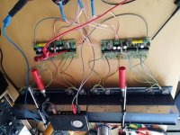
It's not finished yet, it's hooked up to 25 volt 80000uf pr channel, I'm waiting for a capacitance multiplier pcb, and I've ordered 4 capacitors 35v 47000uf that fits pcb.

I intend to build the 15W dual rail version (+22V 0V -22V DC) my rails may be a bit high even under load (yet to be determined) but I could then build a regulated supply. Also I may make 4 channels. So that should take up some of the 'overkill'. Plus the 400VA is an estimate, someone on another thread suggested that it may be 300VA. Which Class A amp - help me decide.
I based my estimate on the esp website Transformers Part 2 - Beginners' Guide to Electronics. I'm still thinking things through so I may use just one Tx and save a bit of space.
That is the version I built. Because of my experience with my 1969 build the EI laminated transformers made locally the first one rated at 80 VA burned out.
I replaced this with one rated at 150 VA which also burned out this induced magnetic fields which caused the case to buzz at mains frequency and the service life was shorter than the original 80 VA from the same company.
For that reason when I built the 1996 stereo version I specified a toroid rating of 300 VA for a stereo pair. This had two 22 V ac secondary windings.
While this has been reliable it does run rather hot due under continuous load and close to the supply voltage regulators - whose transistors also dissipate quite a lot of heat.
If I was building this from scratch now I would consider bigger heat sinks for the amplifier and regulators and a higher VA rated transformer.
If you are going to make a four channels you will have even more heat as well as a problem of housing the bulk of everything in a respectable looking case. I had to house the transformer and voltage supply regulator in a separate box - there are four large 15000uF capacitors and with the transformer and the supply regulator board with heat sink, occupy a lot of space.
I put a link to the NAD 3020 up. One way it beats nearly everything is using tough transistors with imagination. The ability to offer current from nowhere is impressive.
An idea I have played with on paper is a Darlington VAS at high current with CCS. 50 mA ? This mimics the JLH and simplifies things. A T0220 with small heat sink might do. A BC337 with 2SC5200 with no heatsink. No absolute need for a feedforward resistor as it's a class A stage. Like the JLH a small one perhaps? In this use more feedforward than discharge device.
A Naim NAP 140 input stage with fake singleton input ( 22K 1K ). TIP2955/3055 ( perhaps parirs with 0R1 emitter resisors ) Bias set to 0.5 amps.
The bias would be crude as 0.25 to 0.6 Amps is fine.
Class A > 1 watt >2ohms
AB 30/55/100 8/4/2. These are music watts and not driving a resistor watts. Techno music 33%. 16 % other types. Hypex say 10%.
I think the VAS amp would have to have a very quiet PSU.
This is the amplifer that Douglas Self says is as bad as it can get. Maybe yes except on music?
Never say anthing is a bad idea without trying it. Out of need I made a USB 5V to 12V converter using NE555 and 500 uH choke. When running 52/48 ratio 60V free running. I reduced this using 67/33% 1K 1K 10 nF. 24 V and 17 V on load. The switching a BD135 with 1K base resistor. A guy had designed this and rejected it as he hadn't worked out the rest. A very nice guy from Maxim helped. In my opinion doing what I did was right. I simply put a 7812 regulator on to it, him a zener. At first I did this to see if it could fly. It seems the 7812 loves this use. It went supersonic! After a tiny bit of oscilloscope work it has no real defects. The residuals are -60 dB and very pure. Now the warning. This version sounds better than a linear supply with 7812!!! Reason is a hum loop somewhere ( - 70 dB ? ). Some of the residual is from the USB so remarkable. This PSU would easilly become a class D idea. Pin 5 modulated giving 0.3 watts. If wanting more a deadband has to be engineered.
Didn't have to wait long for the first howler to appear: paragraph three.
"A first-principals approach is preferred and adhered to whenever appropriate."
"A first-principals approach is preferred and adhered to whenever appropriate."
- Home
- Amplifiers
- Solid State
- JLH 10 Watt class A amplifier