Hi guys! Just a quick tip if you want to try new transistors: buy original SanKen 2SC1116 ones, they have a wonderful sound. I've used them in my Hiraga Le Monstre 8W and my JLH 10W, and they definitely sound better than the 2N3055s or the MJL ones.
Hello,
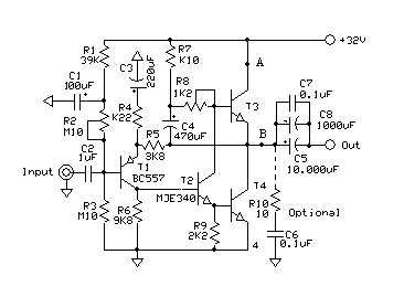
I am building this amp acording to this schema:
The first channel I built works fine and sounds fantastic, but I have large dc offset at second channel output.
PSU voltage is 22V, by trimming R2 I can get DC at the output anywhere between 10-17V, but I cant get rid of it. I checked all output caps and they are good.
Any ideas?
Such high DC offset is normally because T3 and/or T4 are defective.
Also, your Zobel (R10, C6) is usually located at the Output and not at point 'B'
Good luck,
Eric
Also, your Zobel (R10, C6) is usually located at the Output and not at point 'B'
Good luck,
Eric
Last edited:
Cerniu
Try to add let`s say some 470-ohm 1/2W resistor from output + terminal to ground line ,
turn on your amp ,wait several seconds ,and than check DCV across output terminals again,
since is easy possible that your voltmeter have way to high internal resistance and can not fast enough to discharge pretty big value(11.000uF!) of output capacitors stored charge .
Regards !
Attachments
Last edited:
Post3304 is a single supply amplifier with the Input and Output AC coupled.
Point B always has a voltage above ground. At no output current point B is at roughly half supply voltage.
The Coupling/DC blocking capacitors block that DC voltage and prevent that feeding into the load.
Any leakage through the Coupling capacitors will be measurable as a DC offset at the OUT terminal.
This arrangement always uses a grounding resistor to take that leakage current to PSU ground.
Fit a grounding resistor from OUT to PSU Ground, use a value >>load resistance and maybe 100*load resistance.
Low leakage capacitors could use >100k, but electrolytics will need a much lower grounding resistor.
Once that is fitted the output offset at OUT will be near zero milli-volts.
Hello,
I am building this amp acording to this schema:
The first channel I built works fine and sounds fantastic, but I have large dc offset at second channel output.
PSU voltage is 22V, by trimming R2 I can get DC at the output anywhere between 10-17V, but I cant get rid of it. I checked all output caps and they are good.
Any ideas?
Hi!
I would set it to 11 Volts, then connect a few hundred Ohm resistor to the output pins, and measure again.

Thank you for quick replies. I was scared to hookup 10+V DC to speakers, but it turns out, just as you said offset is like 5mV with load connected.
Both channels are running, sounds much more detailed and bass is better than my LM1875 amp.
Superb! Yes, the bass is massive on the JLH amplifier, i've noticed that immediately after i built it.
Hi all you JLH people!
I have spent many a happy hour wading through this thread and have just built my first JLH 1969 amp from an ebay kit. I must admit to being very pleasantly surprised! I initially powered it up with a couple of 12V 2A "wall warts" and found that even at this low voltage my floorstanding TL speakers were rumbling the room. Iq was about 600mA and the heatsinks were barely getting warm. I then switched to a 24V supply (Iq about 1.5A) and my barely adequate heatsinks got quite hot to the touch without too much more noticible increase in volume. I backed off the Iq to 750mA and the HS temperature stabilised at a level where I could comfortably touch.
This got me wondering.... I know the suggested Iq is around 1.2A but how is this determined? What are the negative effects of having too low an Iq? (TR1 & TR2 are 2SD1047C's)
Hi Colin, This is just from memory but the output stage standing current in the original '69 version did come in for a little comment after the article was published. As you say it was 1.2amp
One correspondent in the WW "Letters to the Editor" section said it did the cause of class-A a slight disservice. When calculated to supply 10 watts into 8 ohms the figure comes out at around 900milliamps. (The correspondent, Nelson-Jones, subsequently published his own similar 10 watt design in WW with a standing current of about 900mas.) JLH replied that he did know that (!) and he was "erring on the side of caution". I think he gave three reasons. One was to allow for real world speakers that frequently have an impedance less than the stated "nominal" figure i.e. an "8ohm" speaker may dip to 6ohms etc and a higher standing current will allow class-A op to a 10w level under these conditions. Another was to do with current gain characteristics of the output transistors I think and as I don't have the material in front of me the third reason eludes me at the moment.
I'll chase it up.
Cheers Jonathan
The place to go for all these and other questions is a site created by Geoff MOSS. It is "The Class-A amplifier site" go to "Main Index", then "Other Class-A Amplifiers" and you'll find the L Nelson-Jones design there and he talks his readers through all the design theory in a v helpful way. There you will get the calculations and the theoretical figure for 10 watts into 8 ohms as 875ma.
Cheers JB
Cheers JB
Last edited:
A normal classAB amp with high standing current, will output class A power upto the standing current limit and afterwards will slide into class AB. JLLH amp, due to its topology, cannot output power beyond the standing current level. Hence, JLLH chose a more conservative standing current.
Thanks Jonathan for pointing me at "The Class A amplifier site", very interesting reading. I've set Iq at 900mA for 22V supply and will see how it goes. I might even get the chance to put a 'scope on it to check its performance.
your heatsinks are too small.Hi all you JLH people!
I have spent many a happy hour wading through this thread and have just built my first JLH 1969 amp from an ebay kit. I must admit to being very pleasantly surprised! I initially powered it up with a couple of 12V 2A "wall warts" and found that even at this low voltage my floorstanding TL speakers were rumbling the room. Iq was about 600mA and the heatsinks were barely getting warm. I then switched to a 24V supply (Iq about 1.5A) and my barely adequate heatsinks got quite hot to the touch without too much more noticible increase in volume. I backed off the Iq to 750mA and the HS temperature stabilised at a level where I could comfortably touch.
This got me wondering.... I know the suggested Iq is around 1.2A but how is this determined? What are the negative effects of having too low an Iq? (TR1 & TR2 are 2SD1047C's)
Invest in some big sinks. Your JLH deserves better.
I don't know how you got that 875mA value but it's wrong.The place to go for all these and other questions is a site created by Geoff MOSS. It is "The Class-A amplifier site" go to "Main Index", then "Other Class-A Amplifiers" and you'll find the L Nelson-Jones design there and he talks his readers through all the design theory in a v helpful way. There you will get the calculations and the theoretical figure for 10 watts into 8 ohms as 875ma.
Cheers JB
P=I²R=V²/R=IR for constant DC
For sinewave signals the formulae need to be modified to become:
P= Iac²R= Vac²/R= IacVac for rms value of the sinewave
or
P=Ipk²R/2=Vpk²/R/2= IpkVpk/2 for peak value of the sinewave, (not peak to peak).
875mAac gives 6.125W
875mApk gives 3.0625W
An 8r0 test load needs to see 1.581Apk (=1.118Aac) for 10W
An 8ohms 2way (and multiway) speaker can draw three to five times that test resistor current on fast changing transients.
i.e. a 10W 8ohms amplifier may need to deliver upto 5Apk to properly drive a reactive 8ohms 2way speaker without current clipping.
A full range speaker without any crossover, nor any speaker zobel, may draw upto 150% of the current into a test resistor. That makes a 2.37Apk output into an 8ohms full range speaker typically clip free.
Last edited:
Thanks for the info Andrew. I realise the heatsinks are inadequate but it's what I had at the time and they're fine for while I'm experimenting. A PC case fan with natty LEDs keeps it cool while it's powered up. Runs off a 6V battery pack and it's completely silent. (may also experiment with a couple of CPU coolers)
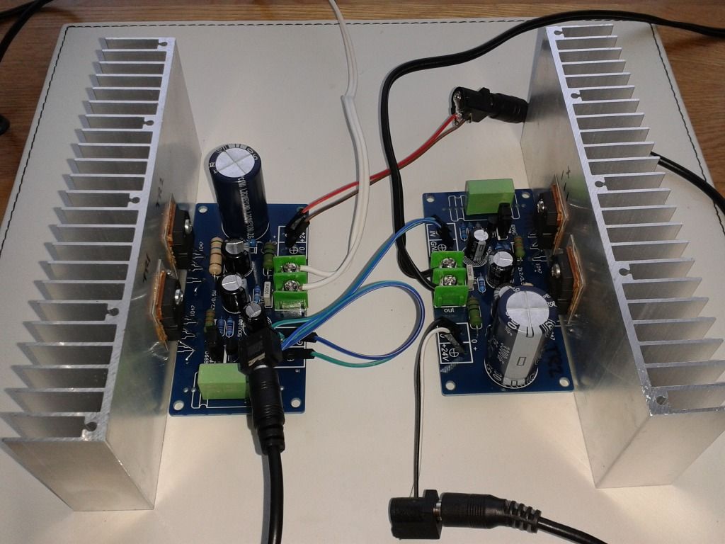
http://i570.photobucket.com/albums/ss143/colinmel/2016-01-22 11.01.37_zpsyoa2uv38.jpg
I've got a case lined up for this amp with much beefier heatsinks and a couple of Roederstein output caps waiting to be hooked up. Which prompts another question... does it really make a audible improvement to parallel up output capacitors? ie 3300 // 330 // 33 // 3 // 0.3uF ? I've read about this technique and may give it a try as it's easy enough to do.
Last edited:
No........................does it really make a audible improvement to parallel up output capacitors? ie 3300 // 330 // 33 // 3 // 0.3uF ? I've read about this technique and may give it a try as it's easy enough to do.
Separate out your supply rail decoupling into HF and MF. Make each as big as required.
Then let the PSU do the LF.
Since all the MF and HF are done on the PCB right next to the devices that will demand the faster transients, there is no advantage to adding extra (small) capacitors at the far end of long cables.
Hi Colin,
Andrew says the right things.
A good psu is important for the jlh69.
With bigger heatsinks you wil have an amp that never leaves you.
Andrew says the right things.
A good psu is important for the jlh69.
With bigger heatsinks you wil have an amp that never leaves you.
Hi Andrew, as I said, I am not an EE by training but I got the 875ma figures straight from from L Nelson-Jones 10watt amp "WW" article that was reprinted on Geoff Moss's website................
It's on page five if you want to check out his reasoning. Btw that's Geoff's page numbering not the "WW" edition. It looks like he went to the trouble of re-typing the original print version for his digital version.
Cheers, Jonathan
It's on page five if you want to check out his reasoning. Btw that's Geoff's page numbering not the "WW" edition. It looks like he went to the trouble of re-typing the original print version for his digital version.
Cheers, Jonathan
Last edited:
- Home
- Amplifiers
- Solid State
- JLH 10 Watt class A amplifier