I made my 1969 version too, and have no turn-on-thump. Did you change any values from the original schematic (input bias cap, feedback cap? etc)..
gr,
Thijs
gr,
Thijs
"I made my 1969 version too, and have no turn-on-thump. Did you change any values from the original schematic (input bias cap, feedback cap? etc).."
I use the 2N3055, Input Capacitor change from 0.5uF to 0.22uF, a single power supply for both channels: L-R-L (10000uF-0.5ohm-10000uF) with a 300VA transformer, output capacitor from 2500uF to 3300uF, a 2k ohm resistor shorting the output to ground.
Any advise is much appreciated.
I use the 2N3055, Input Capacitor change from 0.5uF to 0.22uF, a single power supply for both channels: L-R-L (10000uF-0.5ohm-10000uF) with a 300VA transformer, output capacitor from 2500uF to 3300uF, a 2k ohm resistor shorting the output to ground.
Any advise is much appreciated.
millwood said:
they are what I have. In that particular design, about 30ma goes through the collector. so a medium power bjt will work but I happen to have none of them thus the 15030.
Fair enough answer. 🙂 I'm definitely intrigued by the concept and am interested to hear how it ends up.
eL
"Originally posted by Chris Ma
I do not have any switch on thump, it depends on the way, sequence of how I turn the system on.
1/ switch pre-amp on first, use mute and/or select other line source with no input/output.
2/ switch JLHs on
3/ place CD in DVD player
4/ select CD line source and turn mute off
5/ play CD
No thump noise at all "
I have a passive attenuator (5k ohm) built in the amplifier and even with all auxillary equipment off and the passive attenuator wiper at ground, I still experience the thump when the amplifier is switched on. Any ideas why?
Cheong said:with all auxillary equipment off and the passive attenuator wiper at ground, I still experience the thump when the amplifier is switched on. Any ideas why?
If you have built the original 1969 version, when you turn on the amp you have to charge up the o/p capacitor. It seems normal to me that this will give a turn on thump.
I would be interested to hear if anyone understands how anyone with the 1969 version could avoid this.
My way around this is to use two amps per channel in balanced working mode. If the two amps are identical the switch on thump will be totally absent.
mike
mikelm said:
If you have built the original 1969 version, when you turn on the amp you have to charge up the o/p capacitor. It seems normal to me that this will give a turn on thump.
I would be interested to hear if anyone understands how anyone with the 1969 version could avoid this.
My way around this is to use two amps per channel in balanced working mode. If the two amps are identical the switch on thump will be totally absent.
mike
Mike,
I agree with your diagnose. Another way to avoid it would be to go to bipolar supplies, with a servo to null the output DC and get rid of the output cap. But, come to think of it, that may still cause a thump from asymetrically rising voltages and current in the amp. Maybe he should just put in a delayed speaker relay?
Jan Didden
Maybe he should just put in a delayed speaker relay? Jan Didden
It will work provided that the output capacitor is first charged up with another 8 ohm resistor. There will be no thump when the output contacts is change from the resistor to the speaker using relay.
But... we are concerned that the relays may degrade the sound as the smaller sizes relays typically have small contacts.
Cheong said:I am concerned with the switch on thump for my 1969 version. It is used to drive my horn speakers with 96dB sensitivity. The switch on thump causes the woofer to jump out at an alarming amplitude. Any good ways to reduce this or even eliminate the switch on thump?
what impedence are your speakers ?
these high sensitivity speakers are often 12 ohms.
if this is the case, or even if they are 8 ohms, you could try a relay that leaves a 4ohms resistor across the o/p until about 3 seconds after turn on.
I would imagine that with the limited current capability of the amp this resistive shunt would reduce the power going to the speaker at turn on.
what do others think of this idea ?
do you think that it would help ?
what impedence are your speakers ? mikelm
The speakers are LOTH-X AMAZE rated at nominal of 8 ohms at 96dB/Watt.
With capacitor coupled amplifiers, the output capacitor charging
through the speaker causes this thump sound.The way to
eliminate it is to make the capacitor charge slowly.This can be
achieved by running the amplifier from a 'SLOW RISE' supply
or, with very slight modification to your existing setup, filtering
the bias to your input stage with a big R and a big C.
Concerning the 1969 JLH, I wonder if anyone has modified it
such that the feedback loop is divided into 2.One is DC feedback,
just like in the circuit, the other one is AC feedback, taken after
the coupling capacitor.This arrangement partially includes the coupling capacitor inside the feedback loop, ironing out its
negative influence on the sound.
Best Regards
Selim
With capacitor coupled amplifiers, the output capacitor charging throught the speaker causes this thump sound. selim
How about shorting the speaker output terminals momentarily using relay during power up and release the short before the music comes through? Will shorting the speaker output terminals in the beginning of the power up cause any damage to the amplifier?
The JLH 69 design is inherently current limited.Therefore,
shorting the amplifier at startup should not cause any damage.
But this statement is true only for JLH 69 version.Don't try
it with other amplifiers.
Best regards
Selim
shorting the amplifier at startup should not cause any damage.
But this statement is true only for JLH 69 version.Don't try
it with other amplifiers.
Best regards
Selim
Hi,
I am planning on making a 15W JLH Updated version.
I'm still thinking on how to create the PCB for the amp itself, I can't seem to find a good layout.
So, since I was tired of trying to create a layout for the amp, yesterday I tried one for the power supply.
Ok, so, first, the power supply schematic (this isn't on Geoff's site, he send it to me):
The parts layout (96dpi):
The traces (96dpi):
Both (96dpi):
Would this work, or will I encounter problems?
(If this should have been posted in a separate topic, please excuse me, I'm new here).
I am planning on making a 15W JLH Updated version.
I'm still thinking on how to create the PCB for the amp itself, I can't seem to find a good layout.
So, since I was tired of trying to create a layout for the amp, yesterday I tried one for the power supply.
Ok, so, first, the power supply schematic (this isn't on Geoff's site, he send it to me):
An externally hosted image should be here but it was not working when we last tested it.
The parts layout (96dpi):
An externally hosted image should be here but it was not working when we last tested it.
The traces (96dpi):
An externally hosted image should be here but it was not working when we last tested it.
Both (96dpi):
An externally hosted image should be here but it was not working when we last tested it.
Would this work, or will I encounter problems?
(If this should have been posted in a separate topic, please excuse me, I'm new here).
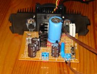
millwood said:OK, here is the mosfet jlh1969 that I put together.
I haven't built one yet and would love to see other's experience with a mosfet jlh.
I completed it today. It is now hooked to a boombox and a PSB alpha. Some impression:
1) it sounded good. In fact, I would put it ahead of my various versions of Gainclone. It sounded "full", with very vibrant bass ("elastic"?), and clear highs.
2) it seems to clip more gracefully than the gainclone. When the gainclone is driven into clipping, it sounded "dry" and "bright". The mosfet jlh1969 starts to sound "coarse" and then "dry".
3) it isn't very powerful. It cannot go even remotely close to where my gainclone can. I guess 10w is a pretty honest number.
4) there is a minor "thump" at power on. and it goes right away. I need to investigate further on this.
5) the Iq is now set at about 1amp. I tried to adjust it up and down (from 0.7amp to 4amp) and anything about 1.5 - 2 amp seems to be pretty much the same in terms of sound quality. However, at 0.7amp you can hear distortion. the heatsink (see below) is such that at 2amp, over 10 - 15 minutes the heatsink is warm to hot to the touch. so I am running it at 1amp now.
6) also, the power-on rush current seems to be pretty big. It blow two 3amp fast-blow fuses.
7) the Iq stablizes within about 20-30 seconds after power on. But it doesn't seem to have any negative / positive impact on sound quality within the "heat-up" period.
The set-up: it is essentially the jlh1969 with two IRF540s at the output. It is now cooled by a Pentium II heatsink (what I have right now), with active fan cooling (I had to make a 12v PS from LM2596). All done on a radioshack board (4x4 I think), using radioshack components too 🙂)). The PS uses one gbu8k bridge, two 3300uf filter caps, and outputs 36v dc (32dc at 4amp).
here is the schematics for those interested:
http://www.diyaudio.com/forums/showthread.php?postid=255436#post255436
the only changes:
1) R11 and R22 are 220ohm resistors. I did short those two resistors and the amp is stable with them shorted. No signs of high frequency oscillation but then I don't have a scope to be 100% about it.
2) R7 is a 220ohm adjustable pot.
more listening.
having listened to my mosfet jlh for a while, the most impressive thing seems to be bass response: very vibrant and "bouncy". this is particularly explicit on track 1 and 7 of "Into the Light" by Chris De Burgh ("Last Night" and "Fatal Hesitation").
It actually surprised me a lot as the jlh is cap-coupled while my other amps are all direct DC coupled and should in theory reach 0hz (on the amp). The Signature is closest to the JLH, followed by my parasound and then my sony ES.
But the jlh needs some power, 🙂. maybe I can raise the rail voltage and parallel more output devices, 🙂
The set-up: it is essentially the jlh1969 with two IRF540s at the output.
Do you realize that you have created a unique, truly unique output stage... I really dare anyone to search and find such a BJT/MOSFET triangle output stage ... That said: my simulation so far tell me that there is a lot more to it that just simply exchange the 2N3055 with some IRF540's ... the gate's are a high impedance junction.. while the 2N3055 are a low imopedance junction.. really the analysis of this particular output stage is not that straight forward... at least that is what I think.. at at least worth a thread on it's own...
really .. think about it...
I really hope someonemore knowlegbeble can comment on the BJT/MOSFET exchange in a JLH 10W Class A 1969 amplifier... it makes my head spin..

I don't recall how I arrived at the particular design but I do recall dropping in the irfs didn't work out of the box. What I did is to increase the current on the driver (mje15030 in my design). I think it runs in the 40ma range now vs. 20ma under the original jlh (I think). Of course, I had to play with R6/R7 (R1/R2 in the original jlh) to make it work.
R10 also is changed to help set up the input stage.
One very impressive thing about this is that there is no signs of hum. and I wasn't particularly careful in the layout nor shielding of wires (all un-shielded wires).
But before I built it, I had no idea if it actually would work. so I am quite happy (and relieved) that it turned out this well.
Again, I would love to hear from more experienced folks here to see how I can improve it.
This is great.
It makes me wonder what the FET version would be like with the full capacitance multiplier power supply that apparently makes a big difference. Or applying some of the recent mods that Geoff has published.
The circuit is so simple, you could bang one together quickly to try it out. Elegant.
It makes me wonder what the FET version would be like with the full capacitance multiplier power supply that apparently makes a big difference. Or applying some of the recent mods that Geoff has published.
The circuit is so simple, you could bang one together quickly to try it out. Elegant.
- Home
- Amplifiers
- Solid State
- JLH 10 Watt class A amplifier