Thanks Geoff and Paul for your clear and concise replies. It seems that the high power version would be a better option as it seems to be less stressful on the output transistors. The 3055s on the 1996 jlh I built gave up the ghost too often.
The pcbs I have are from Williams Hart and are of poor quality, does anyone know of a supplier of pcbs of the layout you recommend? Also for the cap mult circuit. I have no way of making pcbs.
Jeremy
The pcbs I have are from Williams Hart and are of poor quality, does anyone know of a supplier of pcbs of the layout you recommend? Also for the cap mult circuit. I have no way of making pcbs.
Jeremy
I ordered mine from Olimex and am quite pleased with the results. If you need help to submit the Gerber files to them you can email me directly.
http://www.olimex.com/pcb/protos.html
http://www.olimex.com/pcb/protos.html
paulb said:Congratulations! Enjoy!
I've placed all the new information I received from Geoff (schematics, layouts, gerbers, etc.) on my personal webspace at
http://members.shaw.ca/paul.r.brown/DIY/Geoff Moss JLH/
This is the same stuff I posted individually here a few pages ago. Geoff is still planning to update his site but hasn't got to it yet.
Are the output transistors mounted off the board. If they are mounted to the board the pin outs are wrong. It should be B C E.
MikeW said:
Are the output transistors mounted off the board. If they are mounted to the board the pin outs are wrong. It should be B C E.
Mike
The layout was done for output transistors that are not mounted on the board. The pads and holes are sized to suit 5mm pcb terminal blocks so that (short) flying leads can be taken to both TO-3 and flatpack transistors. This gives greater flexibility for alternative heatsink types and keeps the pcb, and board mounted components, a little further away from the hot heatsink surface. It also meant that a virtually identical layout could be used for both single and double sided boards, with the need for only one jumper on the single sided pcb.
Geoff

paulb said:I ordered mine from Olimex and am quite pleased with the results. If you need help to submit the Gerber files to them you can email me directly.
http://www.olimex.com/pcb/protos.html
Thanks for the link Paul.
Does anyone know of something similar over here in the uk?
Also, where can I obtain tantalum film resistors or vishay? How about the exotic paper in oil caps?
Sorry to seem such an ignoramus but it's been years since my last diy fling. It was the days of Farnell having an actual catalogue which they sent me!
J
united said:
Thanks for the link Paul.
Does anyone know of something similar over here in the uk?
Also, where can I obtain tantalum film resistors or vishay? How about the exotic paper in oil caps?
Sorry to seem such an ignoramus but it's been years since my last diy fling. It was the days of Farnell having an actual catalogue which they sent me!
J
They still have a catalogue - but their CD catalogue is very well done and easy to use and most times i prefered* to use this. ( as opposed to their website which is not that great )
*past tense because I now live in the US.
Olimex is closer to you than me, they're in Bulgaria.united said:Thanks for the link Paul.
Does anyone know of something similar over here in the uk?
Oops, I saw the pricing in $ and jumped to the wrong conclusion. I'll send you an email so you can give me a few pointers on how to place an order. Thanks yet again.
J
J
united said:
Also, where can I obtain tantalum film resistors or vishay? How about the exotic paper in oil caps?
J
http://www.audionote.co.uk/kits/resistors.shtml
http://www.audionote.co.uk/kits/cap_paper.shtml
http://www.partsconnexion.com/catalog/resistors.html (please use the page-tabs at the buttom)
http://www.partsconnexion.com/catalog/CapacitorsElectrolytic.html (please use the page-tabs at the buttom)
Best regards
Knud
Transistor matching for high power version
I've been building the chassis for my LJH-update amp.
It took a while because it was difficult to mount TO-3 packages to it. But now that's done and yesterday I was listening to some very nice music (one channel only).
Everything runs nice and cool with rails of 24 Volts and an Iq of 1 A. Plenty of room to make the Iq higher in near future. Maybe I'll drop the rails a little (the cap multiplier supply I use (Rod Elliot's design) seems to give this possibility.
The amp is now running on two 2N3055 (unmatched). I'm planning to upgrade to the high power version using 4 2sc3281's per channel.
Now the question: I know that the output transisors should be a matched pair and if not well matched the device with the higher gain should be in the position of Tr1. But how does that work with paralleled output devices?
Do I need four matched devices or can I somehow average the characteristics for the two transistors in the place of Tr1 and the two transistors in the place for Tr2?
Are there any special requirements for the emitter resistors. I noticed other builders used 10 W film resistors. That seems to be excessive to me. Will ordinary wirewound resistors of 5 W give a good result or should I go for metaloxide resistors with comparable rating?
thank you all
MArco
> Do I need four matched devices or can I somehow average the characteristics for the two transistors in the place of Tr1 and the two transistors in the place for Tr2?
In principle you can average, but the transistors might end up with slightly different bias points. It is best to try to aim for all 4 matched, and then pair them so that the average matches even better.
Only my personal opinion. Someone might not agree.
> Are there any special requirements for the emitter resistors ?
No. Normal 4W metal film is fine.
Japanese DIYers use MPC74 or MPC71 a lot (http://www.schuro.de/preisl-mpc71.htm), and not expensive.
If you match transistors, then you should also match emitter resistors, IMHO.
> I noticed other builders used 10 W film resistors.
I did, because I have them around.
> Will ordinary wirewound resistors of 5 W give a good result
Wirewound has inductance, so you sort of have an extra built-in low-pass filter. Might help stability.
Matter of taste. I use metal film myself. Again only my opinion.
Best to try and then decide for yourself. Resistors cost next to nothing compared to housings ans power supplies.
Patrick
pairing?
How do I do that? Pair 1 high with 1 low gain for Tr2 and 1 high and one low for Tr1 with the average higher than for Tr1 or do I
pair the two with the highest gain for Tr1 and the other two for Tr2?
Thanx again ...
Marco
In principle you can average, but the transistors might end up with slightly different bias points. It is best to try to aim for all 4 matched, and then pair them so that the average matches even better.
How do I do that? Pair 1 high with 1 low gain for Tr2 and 1 high and one low for Tr1 with the average higher than for Tr1 or do I
pair the two with the highest gain for Tr1 and the other two for Tr2?
Do I understand correctly from this tha I can compensate mismatching in transistors with compensating mismatch in resistors. I guess it then has to be that the higher value resistor is in the emitter of the transistor with the highets gain?If you match transistors, then you should also match emitter resistors, IMHO.
Thanx again ...
Marco
> How do I do that?
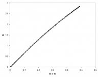
Buy 20 or so transistors and measure hfe, not with a multimeter but drive it with a base current, and measure collect and base current to calculate hfe. Vce should be about you rail voltage, so you need heatsinks for matching.
When you have 4 transistors with about the same hfe, pair them such that the sum of hfe's are closest to each other. But if one pair is still say 1% higher than the other, then use that pair for Tr1.
You may, if you wish, contact me by private email. I have some matched quad MJ15003's left.
> Do I understand correctly from this tha I can compensate mismatching in transistors with compensating mismatch in resistors.
No, I mean when you have perfectly matched transistors, you don't want to spoil the match because your emitter resistors differs to each other by 10~20% ? I measure them as well, and usually you can get metal films to much better than 1% if you buy 50% more and measure them all. This one I cannot help you. I have no 4W 0R1 lying around, only 0R47 metal oxide from Schuro.
Attached a typical measured hfe curve.
Patrick
Attachments
Pretty expensive. I doubt that there would be much audible difference.EUVL said:Buy 20 or so transistors...
You could increase the values of the emitter resistors, and never mind matching the transistors.
> Pretty expensive.
Well, it depends on how little distortion you want (especially in open loop), and how many your are building.
If you are building 2 or 4 amps, then 20 transistors is not much. With a smaller pool, the chances of perfect match diminishes.
I had 35 MJ21194, from which I got 2 good sets of 8. Just for your reference.
Patrick
Re: Transistor matching for high power version
Are we sure these transistors will work in this design without oscillating ?
When I used MJL3281 I needed some compensation.
So some precautions may be necessary
mike
deduikertjes said:I'm planning to upgrade to the high power version using 4 2sc3281's per channel.
Are we sure these transistors will work in this design without oscillating ?
When I used MJL3281 I needed some compensation.
So some precautions may be necessary
mike
> I needed some compensation.
What's wrong with that ?
Someone said on Geoff's website that they got humm with MJ21194.
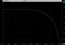
Attached is the frequency response of my Xed JLH with MJ21194 and 10p compensation on the feedback. I can probably get away with 1/3 of that, but this is good enough for me.
And sounds wonderful.
Patrick
What's wrong with that ?
Someone said on Geoff's website that they got humm with MJ21194.
Attached is the frequency response of my Xed JLH with MJ21194 and 10p compensation on the feedback. I can probably get away with 1/3 of that, but this is good enough for me.
And sounds wonderful.
Patrick
Attachments
compensation cap
It is no problem if you do it - could be a big problem if you don't !!!
...and I agree that putting the cap across the feedback resistor is the best method if it works - I did not try that on this design yet
I previously did it from driver stage to i/p tr emitter but I concluded recently that this is not such a good method.
mike
- Home
- Amplifiers
- Solid State
- JLH 10 Watt class A amplifier