dutch diy said:
Chris,
At what rail voltage and bias current were you operating?
I'm running for over a year now on 29.5V and 2.2 A on 4 mj15003's.
During testing of my first J-amp set my Shack Speaker however survived several + an - 22 V DC-offset problems, and not for milli seconds i can tell.
Hi,
For those two years they were set at 20V and 4A and the heatsinks were measured at 55 Celius with no problem. That day when it happened I was listening to them for about an hour or so and I fell to sleep. When the CD ended I woke up and change the CD then I noticed the DC Protection light came on. So I had no idea how long it had happened. I am not sure whether it would have done some sort of damage to the JX150 or not if there was no DC protection. Now I reduced the Iq setting to 20V, 3A to all four mono block JLH.
All heat sinks measured at 41Celius. As I am bi-amping I do not hear much difference whether it is set at 4A or 3A. Before bi-amping 4A sound better than 3A.
Regards,
Chris
Re: Re: preset calculation
What are you using it for?
Erik
mikelm said:
I just discovered that constantan resistance wire sounds MUCH better than thick film resistors
What are you using it for?
Erik
I just noticed that the some of the quote was missing so the post was not as clear as I intended
I am currently using constantan wire as an emitter degeneration resistor 0.1 ohms on the o/p transistor ( the bottom one ).
I was using a thick film resistor before.
The difference in quality is quite dramatic.
( The effect was similar when I swapped out a 0.5 ohm caddock in a cross-over )
mike
I am currently using constantan wire as an emitter degeneration resistor 0.1 ohms on the o/p transistor ( the bottom one ).
I was using a thick film resistor before.
The difference in quality is quite dramatic.
( The effect was similar when I swapped out a 0.5 ohm caddock in a cross-over )
mike
Just a straight piece, about 2 cm or so long? Or wound 'round something? Do tell, do tell. 🙂
E.
E.
The reel of wire that I have is 28 gauge and this gives about 4.2 ohms per meter
a range of gauges can be found here
http://www.wires.co.uk/acatalog/cn_wire.html
4.2 ohms per meter = 0.1 ohms per inch ( 25mm )
How you implememnt this rather depends upon you method of construction. either mount it on blank vero using posts or just put 25mm across whatever gap you have. I would not wind or coil these as this will create inductance.
If you do not already have emitter degeneration resistors you may have to re-adjust you bias current depending of the cct you are using.
I will be interested to hear what you think of this mod
mike
Resistance wire
Maplin also sell it in smaller quantities (an ounce for a fiver - how many ohms per ounce, I wonder?). I'll give it a go.
mikelm said:
I just discovered that constantan resistance wire sounds MUCH better than thick film resistors
28swg is about 4.2 ohms per meter
http://www.diyaudio.com/forums/showthread.php?s=&postid=507054#post507054
http://www.wires.co.uk/acatalog/COPPER_NICKEL.html
Mills noninductive wire wound are also good apparently but I have not heard them and they are much more expensive
mike
Maplin also sell it in smaller quantities (an ounce for a fiver - how many ohms per ounce, I wonder?). I'll give it a go.
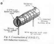
I just want to make a small contribution to the use of "resistance wire". In fact it is actually possible to wind wire in a non-inductive way. This may be useful where it is not possible to find a home for the length of wire you have to use and still mange to keep it in a straight line. It saves space and is quite elegant in its use of physical principles. The only place I know that shows this technique clearly is contained in Geoff Moss's Class-A site. I guess most uses of this thread know Geoff's site. If you go there and then select "Other Class A amps" you will find the Nelson-Jones 10 Watt design. Choose the "article" (not the schematic) link and go to page 12 (of 14). There you will find a delightful diagram of a 0.56 Ohm 5% resistor wound "non-inductively".
Jonathan Bright said:There you will find a delightful diagram of a 0.56 Ohm 5% resistor wound "non-inductively".
To save anyone interested some time, I have attached the relevant figure.
Attachments
Help needed - output dc drift minimisation
I am moving a thread from other site to here, hoping to get more responses to the following question:
I built the JLH Class A on Fig 2- The Final Circuit at www.tcaas.btinternet.co.uk/jlhupdate.htm
Works fine and sounds good.
The problem I have is output dc drift when temperature rises from room to normal operating temperature. The drfit is about 500mV downwards as temperature rises.
Transistors used are as per the circuit except Q3 is BD139.
I adjusted VR1 and VR3 of the CCS as per last paragraph under the heading "Removal of the Feedback Capacitor" in the same Article.
But the iterative process does not seem to substantially narrow down the drift to anything close to 50mV.
Can anybody share his/her experience in making this iterative process??
What should I look for more specifically in slightly adjusting VR3 after the amp has cooled down when making the iterative process.
Thanks
CY
CY,
Your problem sounds rather similar to one that I had. Previously I had got this part of the circuit working well, reducing the offset drift to around 50mV. Then later, having completely rebuilt the circuit on a new board, VR3 had almost no effect whatsoever. This was odd as in the previous circuit I could adjust for either a falling offset drift, or even a rising one if I wanted to.
Can you adjust VR3 from one end of its travel to the other, fairly slowly, whilst monitoring the dc-offset on the amplifier output? In my earlier circuit where the VR3 arrangement worked well, adjusting VR3 like this would result in a dc offset swing in one direction only, for example it would move in one direction when VR3 went clockwise, and the other direction when VR3 went anti-clockwise. However, in the circuit where the VR3 arrangement proved ineffective the dc-offset would swing in one direction and then turn in the other direction during one single complete rotation of VR3. It would be interesting to know if you have the same results.
Eventually I removed VR3 completely, but you could try some ‘slower’ MPSA56 transistors in positions Q5/Q6. These may remove any instability that might be causing your problem and they were very helpful in my circuit where I had subsequent problems in this part of the circuit.
Tim.
CY
To answer your question (which I should have done in my last post) VR1 is used to zero the offset when warm. VR3 should be adjusted such that the dc-offset drift between cold and warm is minimised. To do this VR3 needs to be adjusted when the amp is warm and the dc-offset has stabilised, after doing this allow a few minutes for the circuit (and dc-offset) to re-stabilise before resetting VR1 for zero dc-offset. The amp should then be left to cool down completely and the whole process repeated until a position for VR3 is found (by trial and error) that minimises offset drift during warm-up.
Tim.
Thanks Tim,
I am glad that you have responded and thrown in some light with your personal experience which comforted me that I was not alone.
I am now a bit confused with the sequence of adjusting the VR's.
BTW, the VR's are multi-turn ones.
The process I used was:
1. Amp first time powered up. Output dc was miles away from zero.
2, Adjust VR1 to set output to near zero when cool
3. Amp warmed up. Ouput drifted (can't remember which direction)
4. Adjust VR1 again to set ouput to near zero.
5. Power off. Amp cooled down. Amp powered up again. Output drifted to +ve something like 400-500mV. Amp still cool.
6. Amp warmed up. Ouput drifted towards zero, but not quite zero.
7. Adjust VR 1 when Amp is warm to set output to near zero.
8. Power off, cool down Amp
9. Power on, Amp still cool, Output drifted. Ajust VR3 slightly NOW. GoTo and Repeat item 6 to reiterate the adjustment process.
Basically I adjusted VR1 when Amp is Warm and VR3 when Amp is Cool. Have I mistaken the Ariticle?? Your last Post seems to suggest to adjust both VR's when Amp is Warm.
You also mentioned the "slow' transistors. I shall try some other transistors over the weekend and also the way of adusting VR3 in your first Post and report later.
You touched the subject of stability. My Amp was built in a proto-type manner, using point to point soldering on matrix board. The layout I used seems to me logical. Yet I'll try to get some photo so you may comment on whether the layout is having any stability problem.
Thanks again.
CY
CY,
If I understand correctly you have a rising, then falling dc-offset during warm-up. In my earlier circuit where VR3 worked correctly I achieved a similar result, though as far as I remember the amplitude of my offset rise/fall was much smaller than yours, I think it was less than 100mV.
Is your Iq set very high?
Is there a heat source near Q4, Q5 or Q6?
I suggest you make adjustments to VR3 and VR1 while the amp is fully warm and allow time for the circuit to stabilise afterwards. This way, assuming the amp is fully cold when you next power it up, you will see how effective your adjustments were a few moments after start-up. I suggest that subsequent adjustments to VR3 and VR1 (in that order) should be performed only when the amp is fully warm, allowing time for the circuit (offset) to stabilise between them. In other words, adjust VR3 (through perhaps 45 degrees rotation), wait for the offset to stabilise, then adjust VR1 for zero (or as near as possible) offset. Return a few minutes later to check that the offset has not drifted significantly, re-adjust if necessary, then switch off.
In any case I would change Q5 and Q6 to MPSA56. There have been a few of us who have had problems with this part of the circuit and in my case the MPSA56 solved the problem.
Tim.
Thanks for helping me decide which JLH variant to build. I think I'll keep the cap in the feedback path.
paulb said:Thanks for helping me decide which JLH variant to build. I think I'll keep the cap in the feedback path.
I wasn't sure whether you were talking about a cap-less design, CY.
Were you? Much as I'd like to eradicate electrolytics from the signal path I'm wary of opening the can of worms of DC offset...
paulb said:Thanks for helping me decide which JLH variant to build. I think I'll keep the cap in the feedback path.
bremen nacht said:Much as I'd like to eradicate electrolytics from the signal path I'm wary of opening the can of worms of DC offset...
I am aware of a number of constuctors who have successfully run the JLH without a dc blocking capacitor in the feedback network and some others who have experienced stability problems in the Q5/Q6 ccs when it is required to deliver the higher current needed when the feedback capacitor is removed. The stability issue appears to be layout/wiring related and the chances of a problem can be reduced by using, as Tim has indicated, slower transistors in the Q5/Q6 ccs such as the MPSA56.
Despite my dislike of electrolytic capacitors, I would strongly recommend that the feedback capacitor be retained if you want the amp to work correctly from the outset. However, those that have removed it have reported a small improvement in sound quality so you have a choice - good performance from the outset or marginally better performance with the risk of ccs instability, dc offset problems etc and the possibility of spending time modifying and remodifying the layout/components to find a cure.
I should also draw attention to Rod Elliott's recent article on power amplifier clipping:
http://sound.westhost.com/clipping.htm
which gives details of the increased dc delivered to the speaker under overload conditions when there is no dc blocking capacitor in the feedback path (not that any JLH constructors would run their amps into clipping, would they? 🙂
Geoff
Thanks for helping me decide which JLH variant to build. I think I'll keep the cap in the feedback path.
Well, from my experience the revised circuit we are discussing here, without feedback capacitor and without VR3, has no more offset drift between hot/cold than the standard 1996 circuit. The instability can be avoided and the sound is improved.
Tim.
TimA said:CY,
Can you adjust VR3 from one end of its travel to the other, fairly slowly, whilst monitoring the dc-offset on the amplifier output?
Tim.
I have not done it yet, will do and report result.
TimA said:CY,
Is your Iq set very high?
Is there a heat source near Q4, Q5 or Q6?
In other words, adjust VR3 (through perhaps 45 degrees rotation), wait for the offset to stabilise, then adjust VR1 for zero (or as near as possible) offset. Return a few minutes later to check that the offset has not drifted significantly, re-adjust if necessary, then switch off.
In any case I would change Q5 and Q6 to MPSA56. There have been a few of us who have had problems with this part of the circuit and in my case the MPSA56 solved the problem.
Tim.
Iq was set to close to 2A (0.6V over 0.33ohm). Supply voltage is close to +- 22V, balanced and using cap multiplier.
Heat source is indeed near to Q4, Q5 and Q6. In fact the whole thing is a typical class A furnace. I guess I have problem in the layout in this respect. Will post some photo later for your further comment.
The way you suggested to adjust both VR's when warm seems to yield better result. Over the weekend, I started VR3 at one far end (I think is zero ohm) and iterated the process each time by adjusting VR3 with one or two turns (my VR's are multi-turn ones). Lenthgly process, I am only half way with the VR. BUT...it works!!!!
I already got results of only 80 to 160mV drift between cold and warm. Much better that what I achieved previously.
Need to play around with this process further to see what better result I can get.
bremen nacht said:
I wasn't sure whether you were talking about a cap-less design, CY.
Yes, it is capless, no cap at the output nor feedback path. The only cap in the signal path is the input one. A 1uF polypropelene one.
Geoff said:
The stability issue appears to be layout/wiring related and the chances of a problem can be reduced by using, as Tim has indicated, slower transistors in the Q5/Q6 ccs such as the MPSA56.
Geoff
Had I known the magnitude of the stablility issue before, I would have paid more attention to the layout. Well, I should be able to do something better with the second generation board.
I have not changed the Tr's to MPSA56 yet. These transistors have disappeared in this part of the world. Not even Farnell can source them from its Singaporean or UK warehouse!!!
CY
CY said:
I have not changed the Tr's to MPSA56 yet. These transistors have disappeared in this part of the world. Not even Farnell can source them from its Singaporean or UK warehouse!!!
CY
http://www.donberg.ie/ - also sell the Hitachi transistors.
- Home
- Amplifiers
- Solid State
- JLH 10 Watt class A amplifier