There are certainly Class A designs with lower THD than JLH69. But in some 2 decades of DBLTs, this is the ONLY amp with bla THD (about 0.1% near clipping) that was preferred to supa lo THD amps. provided it wasn't overloaded of course.
IMHO, this is due to the THD profile. I've tried to replicate this THD profile in something which didn't also act as a space heater without success.
So if you just need 10W (tweak for your speaker impedance) and don't mind the space heater, you could do a lot worse than build JLH69. Loadsa info on modern devices etc. and some nice kits.
Using a Meanwell SMPSs would be an audible improvement.

Going crazy with gain adjustments one way or the other is going to invite issues of all sorts, if you ask me. Minor tweaking to meet your needs is all right, though.
It is the experience of many who have been using active crossovers and who wanted to adjust the gains of the LF, MF, HF amplifiers to conform to the power curve, that most amplifiers displayed easily audible 'colourations' when their gains were altered much -- sort of changed "sound signature", even when everything else remained identical. So probably the best ploy is to resort to a simple input attenuator to fine tune your system gains, again, IMO.
If on the other hand, if you are looking for a buffer, leave the JLH well alone and look elsewhere -- the Web offers any number of good power buffers.
We live in fantastic times when almost anything you could dream up could be had on the Web.
If you want a class-A amplifier, a MOSFET amplifier, an IGBT amplifier, a vintage Philips amplifier ... the list is endless, and the Web is your ready source.
A DIYer usually chooses a particular design after considering a range of factors, including personal preferences, the experiences/recommendations of other DIYers etc. So that boils down to the fact that you choose the classic JLH design after reading a lot, hearing a lot and thinking a lot. Times have changed, tech has changed, but we are privy to the shared wisdom of many capable designers and hobbyists to guide us in our build.
Great!
Then, once you get the amp working and playing music, if you are so bent, you could start your "tweaks and mods" trying to squeeze out the "maximum musicality" according to you and your precious ears by resorting to the use of exotic components, fancy power supplies or even fancier facia panels and super fancy heatsinks etc. The possibilities are really endless, and is likely to keep the "devoted hobbyist" occupied for many winters! (the JLH will offer not only audio warmth on such occasions!)
What I have all along failed to understand, try as I might, is this undying penchant on the part of many "designer-hobbyists" to try and "convert" the poor JLH amplifier into all sorts of fancy configurations. Conversion, even when it is something as simple as religious, is not an easy or perfect methodology. JLH designed a basic, good sounding amplifier, using the best that he could apply of the then current technology and topology. You set out to "convert" the classic amp into say, a MOSFET or an IGBT amplifier. You make lots of changes and finally succeed. Kindly pause to ask yourself the question, does your baby sound like even a distant cousin of the original? If yes, fine, post your immortal design, which will be welcomed by many. If not, ...
Plastic surgery is what many who are bothered about the kind of image they project in society resort to often. Not by real audio hobbyists, I think. "Converting" a horse into an *** ... oops! donkey, is all very good if one wishes to advance the state of circuit surgery, but it is probably advisable to seek out an original as that will be the easier option and perhaps will offer the best solution to your problem --that is, IF you have a problem ...
@The Prof
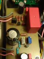
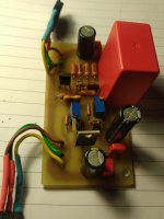
Maybe you also like "Alte Schule".
Although this is not a class A JLH69, the concepts are not really dissimilar. Perhaps you (or your group) will include this amplifier in your program and test it, I would be very pleased.
Apart from that, I would like to thank you for your great blog /page, I also like the JLH classic very much. Somehow it simply represents a standard, "this is what a good amplifier can look like", it simply needs no more and no less. JLH69 is something like a mountain range for me. A rock!
regards,
HBt.
Hi Steveu,JLH 69 has a couple problems. Firstly, it uses the limited gain of the output transistors to set the idle current and limit the output current. So, using "better" transistors gets you into trouble. But the exact gain of any BJT is unpredictable, so you probably have to fiddle with the pull-up, bootstrap resistors (~100x2) to get an appropriate operating current. And as the OPs heat up, that current increases. 1.4 Amps on a 24V supply is appropriate for a 4 Ohm load (1.4x2x4 ~= 24/2) but it is a bit excessive for 8 Ohms, and the OPs are dissipating 1.4x12 =16.8 Watts each all the time, ie hot. Secondly, the THD will be about 0.1%, although it is largely 2nd harmonic which is a sound many people love.
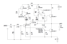
JLH made some better amps later in life, and the 69 reflects the limited parts options available at that time, 55 years ago. Today, the 10W range is mostly cheap chip-amps, but you can roll your own with a handful of penny transistors. Even if you insist on a class-A amp, there are better options today if you are willing to DIY. Others have tried to tame the JLH69 bias problem. Attached is my cut on that idea:
View attachment 1402972
PS: Note the bias transistors need to be larger due to excessive heat, but you get the idea.
An advices for a better class A diy amp?
I would not really agree with this, JLH69 can work with high hFE and fT transistors. My version worked very well with 2SC3284 Y, with 2A quiescent current and +/-22V power supply. I have not had any problems with the stability of the amplifier. This version can be further improved with better CCSs.JLH 69 has a couple problems. Firstly, it uses the limited gain of the output transistors to set the idle current and limit the output current. So, using "better" transistors gets you into trouble.
Attachments
Can you explain a little about the new CCS? Is there a separate thread on this version?This is an improved version, a few copies were made and the owners are delighted with the sound.
The JLH69 is a great amplifier, but we don't need to be slaves to the standard scheme, today it can be greatly improved with new parts.
I actually recommend the use of newer high gain high ft transistors for the JLH. Some great debate a few hundred posts ago about thermal stability though - certainly this option would (in my experience) need a thermal compensation, perhaps along the lines I mentioned which has a temperature dependent current shunt on the driver to progressively reduce the bias current as the heatsink warms. Typically (using 2SC5200's) the Iq started around 1.2A and could reach 1.5A without compensation, even with a generous heatsink. With, it was controlled to within a few tens of mA.
I also found that it required a small compensation capacitor to maintain stability, as grunf shows, but I also kept the bootstrap for maximum positive output.
This certainly gave the best sound (and lowest distortion) from the JLH's I have built.
If people prefer a CCS drive, then I recommend using a higher voltage rail to prevent the voltage compliance limit from limiting the output, but remember that distortion will be increasing due to quasi-saturation near clipping, which you might use as a counter argument to needing a separate higher rail. In my case, I used a higher voltage to offset Q-S with the need for that generous heatsink.
john_ellis, are you saying the original 1969 bootstrap gives the most output into HiZ loads before clipping? Even more than eg https://sound-au.com/tcaas/jlhupdate.htm by Geof with CCS ??... but I also kept the bootstrap for maximum positive output.
This certainly gave the best sound (and lowest distortion) from the JLH's I have built.
If people prefer a CCS drive, then I recommend using a higher voltage rail to prevent the voltage compliance limit from limiting the output ....
The JLH Gateway Part-8:
https://jlhclassicdesigns.blogspot.com/2025/01/the-jlh-gateway-to-class-8.html
Do read and comment,
https://jlhclassicdesigns.blogspot.com/2025/01/the-jlh-gateway-to-class-8.html
Do read and comment,
Yes. The minimum voltage a transistor current clamp will be around 0.6-0.7V, and then there is the Vce(sat) of the CCS transistor, which may be 0.2V. The maximum output voltage will then be a Vbe of the OPT lower still.
With a bootstrap, the drive voltage is "booted" higher than the rail, and in principle, the output can reach the rail voltage minus Vce(sat) of the OPT, rather than rail minus Vbe(OPT)+Vce(sat) (CCS) +Vbe(regulator).
Not sure what the purpose of the 330 mohm resistor is for in the Rod Elliot circuit. That could limit the output as another limitation.
JLH Gateway Part-9:
https://jlhclassicdesigns.blogspot.com/2025/01/the-jlh-gateway-to-class-9.html
Work in progress ... do visit again soon for updates !
https://jlhclassicdesigns.blogspot.com/2025/01/the-jlh-gateway-to-class-9.html
Work in progress ... do visit again soon for updates !
The JLH Gateway Part-10:
https://jlhclassicdesigns.blogspot.com/2025/01/the-jlh-gateway-to-class-10.html
Notes galore to guide the builder along ! (Work in progress ...)
https://jlhclassicdesigns.blogspot.com/2025/01/the-jlh-gateway-to-class-10.html
Notes galore to guide the builder along ! (Work in progress ...)
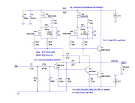
Sure, but you have reduced the VAS current from 27mA to 10mA to compensate for the higher gain OPs. Still, the idle current is defined by the OP gain times that bias current. And the idle current is still temperature dependent. Like others, I initially modified the pull-up to reduce or bias current, but then I realized that is not a great idea. The idle current is actually defined by the lower OP and a 2k2 base resistor is not enough pull-off current for a decent slew rate. So attached is a simulation of an alternate approach that works with a range of OP gain and the idle current is relatively independent of OP temperature.I would not really agree with this, JLH69 can work with high hFE and fT transistors. My version worked very well with 2SC3284 Y, with 2A quiescent current and +/-22V power supply. I have not had any problems with the stability of the amplifier. This version can be further improved with better CCSs.
Attachments
Have you actually tried this? You've turned the bottom output Q20 into a sorta crappy CCS so the max output will have dropped a LOT compared to the true Class A push pull original.So attached is a simulation of an alternate approach that works with a range of OP gain and the idle current is relatively independent of OP temperature.
That's the point of R4. On the negative peak, the "current limit" is about 0.65/0.33 ~=2A while on the positive peak, it's about (0.65-23/12K4 *390)/0.33 ~= nothing. Values were tweaked in simulation, and interestingly the THD is better with no capacitor. OP gain will make a bit of difference but not much. Try the simulation and you will see how it works.

Last edited:
That is an interesting solution - using what would otherwise be a short circuit protection to optimise the current.
It's a similar idea to the one I had where I also used a transistor in your Q1 position, but fed from a temperature sensor on the heatsink.
I also ran the driver current higher, and that helped with slew rate too. Though the highest slew rate I have achieved is with using modern high frequency transistors like 2SC5200/MJL3281A. They may require a small capacitor for stability. Of all the JLH options I have built the HF devices sounded best to me.
The idea of CCS in JLH69 was presented by JLH himself in one of his articles, as well as the idea for dual power supply. Geoff Moss and I were guided by these ideas, with the difference that my CCSs are made with depletion mosfets and his with bipolar ones. Thermal drift is somewhat smaller in my version, but it is still there, which is a feature of the amplifier itself. That thermal drift never worried me because it is a class A amplifier.Sure, but you have reduced the VAS current from 27mA to 10mA to compensate for the higher gain OPs. Still, the idle current is defined by the OP gain times that bias current. And the idle current is still temperature dependent. Like others, I initially modified the pull-up to reduce or bias current, but then I realized that is not a great idea. The idle current is actually defined by the lower OP and a 2k2 base resistor is not enough pull-off current for a decent slew rate. So attached is a simulation of an alternate approach that works with a range of OP gain and the idle current is relatively independent of OP temperature.
View attachment 1405822
I started from the basic version to get to the CCS with depletion. All with tests, and along the way I tested a bunch of transistors in all positions, of which VAS is the most important because it affects the sound the most. By reducing the current through VAS I got a much wider choice of transistors which in the end turned out to be useful because I could use better transistors. The maximum power I pulled out was almost 26W at 8R with +/-22V.
But the most important thing is the power supply and regulators, it makes a huge difference in the sound, just like the 'VAS' transistor.
Attachments

- Home
- Amplifiers
- Solid State
- JLH 10 Watt class A amplifier