He adds fit all or none and why problems may occur. That isn't a solution other than if instability does occur and ,mentions what are essentially layout problems. All sorts will be building it who knows how they will lay it out and connect it up. In some ways it makes sense to kill possible problems because of that at the detriment to performance in this case.I would not recommend JLH's solution
The question of current control in the JLH is an interesting one. The original MJ481 transistor JLH specified was a small chip, low capacitance high fT (at the time back then (4MHz)) device. My now fading datasheet (dated '69) indicates that the gain changes by about +47% between 25 and 175C at 1A. So - if we take the nominal 8 ohm load the operating voltage was 27V at 1.2A. That makes the dissipation in each transistor about 16W. If "room temperature" is allowed to be 50C (and while that seems excessive it is not far off if an amplifier is sitting in direct sunlight) and the junction temperature is kept to 100C that means the total thermal resistance should be 50/16 or 3.125 C/W. The transistor has a thermal resistance of 2C/W, which means the heatsink should be 1.1C/W (without any mica washer, direct mounting, with the insulating problems that brings) per transistor. The drift from 25C to 100C would limit the current change to 24% assuming a linear response. That would mean setting the current to 1A when cold, but obviously you can make some calculations for your own situation and how hot you would allow the junction to become.
Using modern transistors with lower thermal resistances helps, provided the gain change with temperature is known. TIP3055 has a thermal resistance of 1.39K/W but no temp dependence of gain on the datasheeet I have. MJ15003 has a thermal res of 0.7C/W and a gain change of 33% at 1A between 25 and 150 C - the gap closes at higher currents, so would be more stable in a JLH. Neither have the minimum ft of the original (at 3 and 2MHz). I do not know what the fhfe is but it would look like only just surpassing 20kHz if the gain were 100 on the MJ15003, so while it offers more stability and a smaller heatsink (unless you want to increase power) it might not sound as good as the original, but it would be better than the old RCA2N3055.
Thoglette mentioned that he would keep his JLH power supply. That is a good move. It is only a capacitance multiplier, and its current is set, as in the JLH, by the gain of the transistors. Disregarding, for the moment, that the gain of the transistors in the power supply will change with temperature, also depending on the heatsink used, there is an interesting behaviour in the current drawn by the amplifier.
The first point is that as the amplifier warms up, and the quiescent current rises, it demands more current from the power supply. Being fed by a limited gain transistor pair, the voltage will fall and to some extent will oppose the current rise in the amplifier, but of course with a penalty of limiting the peak output power.
As many of you know, the JLH exploits the push-pull arrangement in the output stage to cancel the largely second harmonic distortion each device generates through the gain non-linearity with current. The residual distortion is also partially balancing the second harmonic distortion created by the PNP input transistor which operates at a relatively low current and undergoes a significant current swing at full output. The supply current in the positive wire feeding the amplifier (and this is the 1969 original design I am discussing) will not remain constant, but reflect the average current draw. As the upper output transistor exhibits a significant non-linearity the current actually reduces with full output compared to the quiescent condition. Further, the output transistor dissipation will reduce as power is delivered to the load, and so when in use the transistors will cool down.
That brings me on to the MJ3281 class of transistor. Because the gains are far closer to linearity than the old generation transistors, the average current drawn on load compared with no load is not very different. That would make a simple choke filter even more beneficial. And, as a reminder, in this thread many moons ago I reported simulations showing that the slew rate using these devices is a lot better than any of the 2N3055-type transistors (and I refer to epi base types). Therefore, with the lower distortion, more uniform current draw, and better frequency response I would say that these should perform better than those older transistors.
Finally, that raises the question of how best to stabilise these against oscillation. A Tian probe (in simulation)showed that the basic design was stable even when not compensated - that implies that instability reported by many (including myself) could be related to layout and decoupling as the response extends into the tens of MHz. I have suggested a solution to the instability problem. A challenge, I think, is to develop a scheme which works well - but, and this is a big caveat - does not degrade the performance of the amplifier in the audio spectrum. I suggest that JLH's alternative stability components is not one I would recommend.
What about MJ15001 ,maybe we can supply them in a better price.It may be better than TIP36C

It's been done with a comment that it improves linearity but no test data to prove it achieves anything.I suggest it would have been better to have had a more standard CCS.
A later comment from him on power transistors
My original design is shown in Fig. 1. This is still a valid design, except that the MJ4801481 output transistors are now obsolete. However,
they can be replaced by the more robust 2N3055. In this case, the epitaxial-base version of this device should be chosen rather
than the hometaxial, since the IT of the output transistors should be 4MHz or higher.
Fig1 is the adjustable version of the original. I have wondered if this came about due to more than 0.25v error in output voltage down to severely mismatched transistors that the feed back and drive circuitry can't cope with,
An interesting comment about how the amp came about - 😉 for valve lovers
To be fair, the differences between any of these were not very great - but they were audible. Once they were noticed, they tended
to become more apparent on protracted periods of listening. Certainly, for me - and I was doing these tests for my own benefit - in these
comparative trials, the two best were the Williamson and the class A. They were virtually indistinguishable. Of these two, the
Williamson was vastly more massive and costly to construct. The only remaining question was, if I replaced the 15W Williamson with the lOW
Class-A design, would the output be adequate? Connecting an oscilloscope across the loudspeaker terminals showed that I seldom
needed more than 2-3W from the power amplifier - even under noisy conditions. I suppose that the final proof of my satis
faction with the class A transistor amplifier was that, a year or so later, I gave my oid Williamson to a friend.
🙁 The amp is not much use to me now. I'd need a 4 and 8ohm version but after a fashion it could do both.
John Linsley Hood also said that "smooth 6dB/octave" roll-off would occur when the 1nF capacitor is connected between the collector of the driver transistor and the emitter of the pnp input, along with the other additions. That is an incomplete representation of what happens. When a feedback capacitor is used in this way the lowest gain which can be achieved is unity, until the open loop of the amplifier reduces the gain. You have to use an inverting configuration, or a Miller capacitor to achieve a contiguous 6dB/octave roll-off. So initially there is a 6dB/octave roll-off, but it flattens at 1MHz - which I imagine was what he intended, but his statement implied a continuous roll-off. There is a potential spike at 10MHz, and that spike increases when you use high frequency transistors, so indeed a second roll-off mechanism is required. That necessitated his second 1nF capacitor and series 100 ohm resistor. Finally, his additional RC network on the output does what I mentioned - at high frequencies, it loads the amplifier in parallel with any loudspeaker. Admittedly signals of 1MHz or so are unlikely to be present, but in a Class A circuit there is no margin for additional current to drive the load, so I asuggested this was, in itself, an additional burden.
In my proposed solution (to be tested) I suggested a smaller compensation capacitance than 1nF - not throwing away a usable bandwidth - and resistors in series with the output transistors to suppress the spike I mentioned rather than burdening the input transistor when it has insufficient current to provide a signal for the capacitor at higher frequencies. I also mentioned including the inductor (which JLH discussed but dismissed) with the appropriate value to increase the output load impedance when the capacitor reduces it. I also suggested limiting fast input signals with a low pass filter on the input; something NanoFarad suggested could be added to the original compensation scheme, but that seemed unnecessary when JLH had limited the bandwidth to 50kHz.
One use for such a filter is if you live near a transmitter where cables might pick up RF, but in an integrated amplifier system that would seem unnecessary. I include it because the amplifier gain using high frequency transistors is still inherently around unity past the MHz band so an RF filter could help suppress any local feedback induced effects of the sort JLH discussed.
Last edited:
I built my first JLH in 1972 on what was called [perforated board. Unfortunately, over the 50 years or so the component legs rusted off, and eventually the thing was not working any longer and a year or two ago I decided to make a professional PCB and rebuilt it, designed a SMPS specifically for it and made no mods other than using BD139 as driver and use 2SK1058 and 2SJ162 for the output pair. I had not a moment of regret, and it is still working in the reception that I visit infrequently, with it permanently connected to Spotify and playing music 24/7. I have no qualms with JLH or whether he was capable of designing the amp or not. Furthermore, I liked the sound of the Lateral MOSFETs more than BJTs, and so does the employees at my old business. It is running a vintage pair of original Rodger LS3/5A which is more or less from the same era.
The output devices you mentioned are a complementary pair, so did you change the output to run them in a complementary output stage?
With those LatFETs you could use a simple bias resistor to set the quiescent current as they had an NTC and would have been stable or even reduce the current slightly as they warmed up.
With those LatFETs you could use a simple bias resistor to set the quiescent current as they had an NTC and would have been stable or even reduce the current slightly as they warmed up.
Maybe another quote from the man may help
These are, in fact, better than the curves published in April 1969. As mentioned in a letter to the editor
published in October 1969, the h.f. fall-off shown was mainly due to an error in the measurement
instrument. Although the performance at h.f. depends to some extent on the layout employed, the small
signal voltage gain, with the component arrangement shown, is flat (within 1dB) to beyond 2MHz. This
may be a snag in some cases because even a small feedback capacitance between output and input (as
may happen, for example, if the output heatsinks are not earthed) may cause the amplifier to oscillate. A
suitable circuit change to reduce the amplifier h.f. response to more normal levels was described in the
letter above. This is not an essential modification – the author’s own units are still exactly as described in
April 1969.
The output power response of the unmodified amplifier is flat within 1dB to 200kHz.
Couple of others
Some criticism has been voiced because there is no specific control over the output current value in the
simplest form of this circuit, other than that due to the stability of the current gain of Tr2, whose
performance determines this parameter. In order to meet this point (in anticipation) a circuit was
described in the original article which allowed precise control over the operating ‘quiescent’ current
without detriment to the performance of the amplifier.
However, measurements made on an amplifier without this addition have shown no significant change in
operating current in somewhat over two years use, and there is also little measurable difference in
current from a minute or so after switch-on to the end of a six-hour period of continuous use. In practice
therefore, in temperate climates at least, the simplest form of the circuit is adequate in this respect. If any
However, one transistor change which is recommended is the use of a 2N1711 as Tr3. This has a high
voltage capability equal to that of the 2N1613, and a current gain which is double that of either the
2N1613 or the 2N697. The use of the 2N1711 instead of the former types suggested for Tr3 increases
the feedback factor and approximately halves the typical distortion factor of the system (0.025% at 9W or
0.05% at full power) without detriment in other respects.
His compensation for capacitive loads on this article are dotted as may not be needed. 100R 1n off TR4c and 1n off TR3c to TR4e and 8R2 50n on the output. All or nothing. Interesting aspect.
The author has had the benefit of an extensive and frequently helpful correspondence with readers
following the publication of the circuit design. Attention has been drawn to some obscurities in the
original article and to certain possible improvements in the design. Details are given below.
Design by committee and worry about problems that he hasn't had. Some who contacted him expect the capacitance multiplier to work like a regulator with no load.
Some copies of the article mention adjusting the 100k to ground on TR4 to set the output voltage. He apologies for not detailing that. Sounds like kits may have gone out with a pot.
The later 15w version, fully regulated split supply may outperform the earlier ones.The 15w matches the Williamson. Some people may want that. Speaker efficiency as has been mentioned.
I would just develop a circuit board to test the different circuits. A final amplifier would certainly be built without a circuit board, and would also sound better. So prepare inputs for all four transistors, then local feedback (collector - base Tr1, Tr3, Tr4, emitter base Tr2, Tr3, Tr4), regional feedback (output - T3), emitter and collector resistors for Tr1 and Tr2 and more. Just to be able to offer a lot for the kids to try out. Because this circuit is perhaps the most versatile and interesting in analog, and offers endless possibilities to learn: 3 stage se, 2 stage se, 1 stage se, Follower, "Quasi" Push Pull and more.cumbb, which could be the new schematic, following your advice?
I'm gatering all the infos available for a new JLH 1969 pcb.
To get to the bottom of the circuit, the usual terms of amplifier electronics theory are not enough. We have to look more closely and differentiate, contrast, find new words:
Push Pull is a term that names many things unnamed, unknowable, at least: half-wave separated construction, half-wave separated process, half-wave separated result (... one stage, some or all stages, with or without feedback, including psu or not and so on). I offer other templates: half-wave symmetrical: half-wave symmetrical construction, half-wave symmetrical process, half-wave symmetrical result (... one stage, some or all stages, with or without feedback, including psu or not and so on), to order circuits by real and by quasi pp. And now put them on our JLH;-)
I think most audio electronics enthusiasts come across the wiring of Tr1, Tr2, Tr3 at some point in their thoughts. Simple theory predicts a balanced circuit. Practical and more detailed theories show a different picture: even in the 60s, the aim was to save material and energy costs. So increase the efficiency: "bootstrap"-cap, sonically a step backwards. Then there is the phase inversion of the signal - most speakers have crossover components inside, which can worsen the sound considerably when laying on earth wire. Sonically, the Tr4 is a step backwards. A reference to changes in distortion quality is a following step.
Like this;-)-;
cummb, I would just develop a printed circuit board to test the different solid-state devices I have read about so far. 2N3055, MJ15003, TIP35C and so on. I also have some MJ480s to try out.
Maybe trying mosfets as well, in the output stage only.
Your approach is more complicated than mine.
In any case, I am very curious to see your schematic.
Maybe trying mosfets as well, in the output stage only.
Your approach is more complicated than mine.
In any case, I am very curious to see your schematic.
With what, exactly?Maybe another quote from the man may help
I don't think there is any doubt that the amplifier works with transistors with ft's in the 4Mhz region. What I am discussing is the best option to ensure stability with modern linear gain high speed transistors which JLH did not seemingly manage to address before they came widespread. I haven't claimed a circuit which has been tested in this configuration, only basing it on what I see in simulation, but I have suggested his solution to reduce high bandwidth is not desirable - as he pretty much said himself as you point out in your post.
Pic 1:... to test the different solid-state devices
In any case, I am very curious to see your schematic.
Test of sound character of transes easy in sketch 3, 4:
The resistors circled in orange could be omitted. Step by step;-)
Do not use wire resistors.
Uses only two legs of the trimmers.
Positive feedback in followers or current source is feasible (orange sun). Also works sonically comparable Darlingtons.
Pic 2:
Test of sound-character of diodes and power transes:
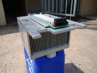
Power diodes and power transistors simply inserts into the power supply. Either instead of the original (1) or, if e.g. transistors do not survive this application, simply in the middle, whether before or after the capacitors or filter coils - no matter (2). Something like seen below.
Attachments
![DSCN0214[1].JPG](/community/data/attachments/1077/1077372-e4ac3154dfcb0593039e685bd5b61285.jpg?hash=5KwxVN_LBZ)
![DSCN0267[1].JPG](/community/data/attachments/1077/1077373-0ccb8ae146cfaf2d48fa84e7bfc57495.jpg?hash=DMuK4UbPry)
Simulation can only show so much. Problems with strays become apparent when something is actually built.With what, exactly?
It looks like there isn't much of a problem finding suitable output transistors with ft ~30Mhz aimed at audio amps. To achieve that things need to change compared with say the 2N3055 version that no on makes now. Various capacitances is one aspect that needs to change.
On the other TR that is a bit of a problem - a modern SOT packaged part could probably offer 100MHz and more gain
It looks like the gains are likely to be higher on all parts as well. That means more feedback factor and as he mentions likely less distortion.
Instability definitely does comes into it when the feedback loop is closed due to phase shift and maybe delays. Hopefully simulation can show that but parts vary, The faster output transistors should help with that. Strays - more and more of a problem as bandwidth goes up.
If it does need slugging the increased open loop gain can still have it's effects.
So far I haven't found anything worth replacing TR4 with other than the G version. I do think the later input filtering is a good idea to try and keep HF out of it. 🙂 It might start receiving long wave. Shortwave too which needs less wire.
The Topology is incredible simple and inherently stable, otherwise in numerous examples C8 has been added to
Designs, and 18p to 27p is more than enough to stabilize amplifiers using output devices from 4 to 35 MHz
Using typical 24 volt laptop supply's around 3 to 5 amps and adding multiple modern high gain power devices you'll likely get almost
2 more volts output. Compared to the typical examples using older TO-3. Basically just use a low Ft T0-3 for the current source
to keep it stable. The amplifier works rather well. Same old " Magical" 2nd Harmonic and the usual .1% distortion @ 1kHz 10 - 12 watts
Using the original Bootstrap current source at cold start Idle current be around 1amp and as the devices reach 40c or higher temp
climbs to 1.3 amps which is about what is needed for full clean power.
obviously you should add power supply decoupling and if using a switch mode laptop supply. Switch mode likely
wouldn't tolerate much more the 450uf to 1000 uf max
Last edited:
He uses the same power transistor on the supply. That means 3 available and more chance of selecting more closely matched gain transistors for the amp. The heatsinking is needed so that could be done at the required current, Same if a stereo amp is built. If some one wants to actually build a regulator for it the same transistor could still be used,
Given his reported frequency ranges I wonder if some small caps need adding to decoupling and the AC feedback electrolytic. Especially that one. Bootstrap too 😉 I wonder but think so.
Given his reported frequency ranges I wonder if some small caps need adding to decoupling and the AC feedback electrolytic. Especially that one. Bootstrap too 😉 I wonder but think so.
For the most part yes, its simplified and power supply decoupling would use the usual large/small capacitors.
And another basic RC network to decouple the gain stages better.
Real life Caps are close to Power transistors.
The low frequency phase reversal of a bootstrap is more than evident and normal for a bootstrap.
small value caps wont do much for a bootstrap. Dont like phase behavior or bootstrap, couple 100 examples
on the net were people get rid of the bootstrap and use feedback CCS. Distortion be the same old .1%
does nothing.
Far as phase margin for high frequency stability , Not sure why people get so confused when using high Ft transistors
when it is no different than any other amp. C8 would be well up to 47 or 100p. No differential input. Doesnt need to be very
high for this topology, but real life. Pretty much should end any ringing with a low value. Ive seen people claim it " ruins" the sound.
All based on wild speculation because anything not found in the original circuit gets added...oh no
Feedback loop at low frequency, no. Actually if you had a stubborn amp 47p to 100p across R1 would also work.
I could add a differential input lol, to hear people cry, the amp would ring like crazy. unless you follow basics
- Home
- Amplifiers
- Solid State
- JLH 10 Watt class A amplifier