The base current is set by the phase splitter.
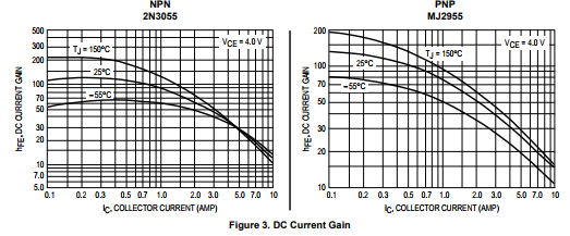
At 3a, hfe falls regardless of the temperature.
At 3a, hfe falls regardless of the temperature.
With the power supply ideas I tried the modern transistors seemed to never completely settle. The more primitive TIP35/36 seemed happier. This was at only 1.2 amps. I guess the base emitter geometry affecting high frequency ability must be linked to gain related to temperature characteristics.
No, it isn't. The division of base current between the two output transistors is.The base current is set by the phase splitter.
The current is set by the bootstrap resistors or the CCS, depending on which variant you use.
The characeteristics you showed also show my earlier comment that at around 1A there is a trade-off between temperature variation and gain reduction.
It would be hard to use a 3055 in class A at 3A because the gain roll-off means the quiescent current would have to be significantly greater than the theoretical Ipk/2.
The lower output transistor 2n3055 receives the base current from the phase splitter. The characteristic Hfe(I, T) falls off 1a. This prevents thermal runaway.
Douglas Self makes a very brief denouncement of a non specific class A amplifier which I narrowed down to the JLH or Sugden. I suspect it was the JLH as he says that the division of current is not assured to paraphrase the argument. I never saw that as a valid reason to damn a genius design. A contraption I would accept .
I noticed that too, and assumed he was discussing the JLH. I thought it rather unwarranted as the current sharing is predictable - if you know the gains of the transistors. In a Class AB where he advocated the use of unmatched pairs, there is even less certainty as to whether the currents are balanced or not!
To defend Douglas he always presents his book as a way to eliminate errors for a production line.. Ironically his really inovative Cambridge Audio design had production engineering problems. I suggested transformer placement might be the cause due to magnetic field distortion. I got the feeling things missed out an evaluation stage. What I never understood is the Self blameless design isn't critised for it's lack of sophistication. The old Hitachi MOSFET amplifier is far more sophisticated albeit having quirks like the JLH. Again whilst not saying directly he denounces double long tail pair designs. The beauty of them is simplicity of sourcing and sinking current and simple constant voltage clamp which substitutes a current mirror. OK the absolute slew rate may be lower due to that but the slew rates of some are due to the asymmetry of the single vas. They need that to get enough in the weeker direction.
Amateur designers, critics and indeed a few professionals from the past, seem to like and trust the visual illusion of symmetry in full complementary schematics. The real silicon doesn't often support that trust but it's the symmetry that seems to inspire our imagination - perhaps more than is warranted.
We could assume Douglas is retired now but I don't think his understanding and practice of electronic design has been narrow in any sense, other than to achieve the lowest THD for the least number or total cost of components. If you saw some of his high performance designs for Audiolab/TAG McLlaren, you'd recognize that they too, were still the same basic design as the textbook Blameless EF version.
Here's a 250W monster example: Tag Mclaren 250MR Mono Power Amplifier Manual | HiFi Engine
Many people refer to a mythical RCA design and laugh at the penny pinched Sinclair Z30. If people are honest modifying Z30 became various Blameless amplifiers. The A&R A60 showed that the Sinclair could be ultra reliable. The RCA was known and was more interesting than the Blameless type. It's finger prints to me are not seen in the supposed clones.ln valve amplifiers the RCA 7199 suggestion design is also the Dynaco. RCA and Millard encouraged use of their parts this way. People refer to the remarkable Dynaco with no mention of RCA.7199 was originally a TV valve they wanted to promote in the Audio version.
Symmetrical double VAS are common in op amps and offer critical symmetry of current drive. True symmetry as some want is horribly complex and might be a mistake due to cancelling nicer distortions.
I often wonder if the Blameless concept is two dimensional and forgets current as the third dimension. Self says any defect in the 3D so to speak will show up in the 2D. My vision of his point of view. I tend to agree except I could imagine finding it could challenge they who don't need to know.
How do you think this jlh compares with pass f5.
I purchased the pass from this website and got it up and running with 6 boards as a 5.1 amplifier.
Now am thinking of building a jlh 5.1 amp. How do you think this jlh will compare against pass f5 in terms of sound quality.
I purchased the pass from this website and got it up and running with 6 boards as a 5.1 amplifier.
Now am thinking of building a jlh 5.1 amp. How do you think this jlh will compare against pass f5 in terms of sound quality.
Don't forget an amplifier is a signal modulated power supply. It's a difficult question due to that alone. The JLH works better than it should as the man understood what he wanted. He used his friends to listen with him. My measurements suggest it has exaclty the right balance of distortion. This was understood in the 1950/60s. Now few seem to. I suppose if a motorcar it would be an original Mini except more refined.
Can you explain the CCS used on the input transistor at the NFB point, is that not a little senseless and defeats the object completely.
To reduce PSU effects? Sometimes these things are added like fashion items. I have seen more interest in things like this than the real engineering. Voltage amplifiers as seen in transistor and valve designs find a CCS very effective. Current amplifiers might find noise is reduced in the same way as a capacitor and resistor ( yes ). Like cooking it's often what you don't do that is better.
file:///C:/Users/Nigel/AppData/Local/Temp/diyAudio-CCS-beta3.pdf
file:///C:/Users/Nigel/AppData/Local/Temp/diyAudio-CCS-beta3.pdf
These threads need automatic recycling at times. I assume Nico you are thinking of the '96 design. It's already been pointed out that this CCS sets the output rail to zero. Current in the input transistor is needed to drive the driver, so if it were not supplied by a CCS the output rail would be offset by a volt or so as it would feed through the feedback resistor. (And as Nigel says, a CCS can improve PSRR).
Nigel, indeed, I think JLH knew quite a bit. His Class A is indeed subtle in some respects. Having recently read Nelson Pass's FET design he discusses a differential input version. I too looked at that option once and on investigation, simulations revealed that it was worse for at least two reasons. One was that the open loop gain is halved (unless a current mirror is used, which drifts further away from the concept of being "simple") but the other is that the single ended design had a "hidden" benefit: the second harmonic distortion in the input stage compensated for - beta roll off! The differential input stage is more linear, and lost that advantage. So yes, it had better performance than it "should have".
Nigel, indeed, I think JLH knew quite a bit. His Class A is indeed subtle in some respects. Having recently read Nelson Pass's FET design he discusses a differential input version. I too looked at that option once and on investigation, simulations revealed that it was worse for at least two reasons. One was that the open loop gain is halved (unless a current mirror is used, which drifts further away from the concept of being "simple") but the other is that the single ended design had a "hidden" benefit: the second harmonic distortion in the input stage compensated for - beta roll off! The differential input stage is more linear, and lost that advantage. So yes, it had better performance than it "should have".
Last edited:
I can understand the liking of a long tail pair ( LTP ) input. If set up like a Naim NAP140 it might even be as good as a single input. The Naim usues it's LTP as a DC reference mostly with a 1K 22K collector resistors from memory. The Naim is said to be the RCA. It isn't. As Alan Mornington West said it was a design of it's time.
Anyone who has tried to set up a JLH type differential input ( one is common base ) will find it very frustraiting. It isn't easy to calculate where best to go. I guess to lose as little as possible through the feedback loop is prime. This means a low impedance loop which is possible due to the output being ample to supply it. This none the less dictates a careful use of current. Often this completely is against what we have been taught. I am surprised no one has said that the JLH must have slewing distortion. That is a tricky one. Can a class A design have that? I guess it can.
Anyone who has tried to set up a JLH type differential input ( one is common base ) will find it very frustraiting. It isn't easy to calculate where best to go. I guess to lose as little as possible through the feedback loop is prime. This means a low impedance loop which is possible due to the output being ample to supply it. This none the less dictates a careful use of current. Often this completely is against what we have been taught. I am surprised no one has said that the JLH must have slewing distortion. That is a tricky one. Can a class A design have that? I guess it can.
I'm sure, buried in this thread somewhere, I've shown that the JLH does suffer slewing. The slew rate is improved with faster transistors, and the reason is that the slewing is caused by the limited base drive current (fhfe as mentioned more recently). Above fhfe the gain will fall and the output will not be able to be sustained at full power; and if a signal tries to drive it at full power, it will be slewing. The JLH is actually problematic in that the slewing is asymmetrical. THe upper output transistor is limited by its bootstrap. A CCS might pull it faster, but I've not checked. The lower device can, temporarily, acquire more current than it should from sucking current out of the upper device (turning that one off more quickly in the process). So the "down" slew is quicker than the "up" slew.
(incidentally, another issue is that this transient COULD reverse bias the base junction of the upper device beyond it's ratings and cause failure, but I've not seen many reports of this failure mode).
The original RCA 2N3055 hometaxial device (the one with the negative differential of gain with temperature at 1A BTW) had quite a terrible 10kHz (min) fhfe, typically 15kHz, that I was surprised people thought it suitable for the JLH. Epitaxial devices with ft's around 3MHz (TIP3055 for example, or the current 2N3055) have fhfe's around 60kHz, so they would be reasonable for many I suspect. Although I've suggested modern 30MHz type devices should give the best results, they have such large input capacitance that I'd have to re-evaluate, because, once again, the base current is limited.
When I first saw the JLH I said " that can't work ". I saw the 2K2 resistor on TR2 driver and said 320 uA can't be right. It fooled me for a while. I would have never used BC337 if I had understood better. However at 27VDC it was fine and 8 watts output 8R.
Being class A I might guess 1V/uS would be enough. 10V/uS if class AB.
I imagine the driver transistor is in pure transconductance where it's input impedance is lower than the static resistance before it. An amplifying vacuum cleaner.
Being class A I might guess 1V/uS would be enough. 10V/uS if class AB.
I imagine the driver transistor is in pure transconductance where it's input impedance is lower than the static resistance before it. An amplifying vacuum cleaner.

This is my real JLH with triangle waves. I think values are correct. The 100 kHz is not at all bad. The 33pF was required. The Indian 2N3055 ( E ? ) were 20 pence each from Rapid electronics. I think they might be better than average 2N3055H/E. Unlike most people I see my BC337-40 as the critical device. On balance I see this version as the best JLH. 5Vrms seems valid for this test. I think 8Vrms was not very different. The PSU was Meanwell SMPS with clean up filter.
The BC337 is the current Hoover.

I have isolated the current sink and removed things which probably don't influence it much.
It seems to me the simple DC servo loop ( TR1 emitter base fixed voltage ) is more sophisticated than thought. The input stage being first automatically is fast enough.
I haven't noticed people saying modern transistors alter the current much. My hunch is they don't think to ask.
Notice that the bootstrap isn't required to look at this.
If I had offered this at college in the 1970s I would have been told not a reliable way to set up current.
If you build this first then add the bootstrap that might be easier. The bootstrap can be 50/50 or whatever. The JLH gives the maximum voltage swing whilst using a sensible 2200 uF. 50/50 might sound better.
BTW. TR1 is like a long tail pair ( LTP ) halved. The output stage has plenty of current so why not? The common base input two is very fast which helps a feedback amp. LTPs are critisised as having time delay. The JLH is better not worse in this way. LTP amps can be designed in 10 minutes, JLH takes a day?
- Home
- Amplifiers
- Solid State
- JLH 10 Watt class A amplifier