Ehhhhhhhhhhhhhh ...
"Deadbug" is just a fancy name for a "tidy person's ratnest".
So be a rat-punk! Make your nest a spaghetti-mess. Let it sparkle and smoke! If it farts out and dies, poke it with a screwdriver and see if it comes alive again! (etc).
"Deadbug" is just a fancy name for a "tidy person's ratnest".
So be a rat-punk! Make your nest a spaghetti-mess. Let it sparkle and smoke! If it farts out and dies, poke it with a screwdriver and see if it comes alive again! (etc).
"Dead Bug" is a relation of "Ugly construction", terms that have been used for a long time by US amateur radio constructors. Long ago, "dead bug" was quite popular for RF circuits where stray reactances could be a problem. I first saw it in photographs as a kid reading Dad's 1956 ARRL handbook, IIRC. Here's a description and some modern and fancy versions on Copperclad. Not so bad, if you take a little care 😉nigel p- is the Dead Bug described anywhere?
Getting Ugly, Dead Bugs, and Going to Manhattan | Hackaday
Let it sparkle and smoke! If it farts out and dies, poke it with a screwdriver and see if it comes alive again! (etc).
 too good. If it still doesnt work, use a hammer
 as a bug swatter wont work for this dead bug.
Paper and pencil is the start of Dead Bug. To simplify I will choose a legacy device TDA2050. LM1875 also.
These are basically power op amps with 5 pins. +IN - IN V- OUTPUT V+. The thing to do is look at NPO/COG caps and SMD resistors to solder to the pins. Just use the suggested circuit to aid your drawing. You might like to calculate the maximum gain you will need and do that by adding a resistor. The more you draw the better it gets. You will have to workout the best soldering order. What you must avoid is a rats nest. Often for a Dead Bug amp the +/- PSU is easier. On the other hand AC coupled amps protect speakers from DC when an output capacitor fitted. If that choice use the output post to anchor the capacitor.
I would say if a neat Dead Bug circuit is made and by using some thought about stability which should be automatic with Dead Bug it might considerably outperform expectations. Spend plenty of time researching parts. Solder SMD to a wire and tin other end. Then solder on the TDA pins. It's actually easier than big parts very often. I have a condition much like Parkinsons, I can still do it. 1206 size often isn't too big. I like the round ones. Keep anything you can on the PSU or output posts. Some capacitors use screw terminals which can aid design. Keep them very close to the TDA, if so a very small supply decoupling can be used ( 100 uF ). 2.5 mm^2 solid core mains wire is good for PSU. It can be a Dead Bug point for the decoupling. If so go larger on the caps, 220 uF being usual. Use the PSU caps as a Star ground.
Lets say a JLH is used to a full range speaker a TDA could power a bass speaker. A simple passive input filter to set the balance.
PURE TAURUS DUNG !!!
Here's how you can wire a TDA/LM pentawhat/TO220-5 PROPERLY, in mixed SMD/TH technique - AND keep your manly pride ... that would be otherwise lost if an inappropriate modernized and feminized techique be used.
You need a smal terminal strip for this - single row.
You can make a single supply amp this way, which goes easier with smps bricks (like some 50w 36V lambdas or so). The advantage is you can bolt your TDA directly onto heatsink without insulation. (You will need good grounding for that).
Solder 1206/1210 size psu bypass caps directly onto chip legs. 0.1u, 1u, 10u 50V x7r. Then a nfb resistor directly onto chip legs 2-4; size 1206 22k or whatever.
Input bias resistor and nfb gain resistor TH 0.25-watters, go to chip legs. The "other" lead of each these resistors go to the corresponding point on the terminal strip (one to Vb splitter the other to "nfb" cap; as per datasheet schem. Don't ask me, you have your brains to use).
The rest of the circuit; zobel, electrolytics, rail splitter etc go to the terminal strip.
Needless to say, then you make a nice spaghetti-type rat-nest of wiring. A special note: you can pretend that your TDA is now a special "hybrid" type chip - which it is when you look at it this way. (Also make sure your wires arent too short, otherwise the TDA will refuse to oscillate and self-destruckt. There will be no sparks and smoke - utterly boring! So let it all hang loose...)
My recommendation for the lytics is FT-Cap axials (the ones with "gold-ish" print). They look stylish and arent too expensive.
For more enhanced macho flavor, you can zip-tie your wiring. Be sure to use the bigger, domestic/home-type zipties, like the 5 or 7mm types - the 2 or 3mm thinner types will make your amp look like you're a nerdy schoolboy.
The challenge is to keep it neat. Drawing is important. I use a CNC type drawing aid as it is quicker. The PSU and outputs can be a tag strip of sorts. It could take a week to do a good layout.
The JLH looks simple enough to be point to point. It isn't really.
Has anyone got a JLH design run at high voltage low current. It could be exactly what I need for a motor at 90Vrms. It would need >400 V NPN's . Output current 22 mA. Voltage rails 300 to 350 VDC. The advantage of the JLH is NPN's are more common and cheaper. Whilst 400V PNP's exist I feel they are the wrong choice. An input PNP would be fine ( KSA94 ).
I can rewind the motor. Better not to.
I did a low-voltage JLH-type (totem) line driver; single-ended 12V rail. 5 or 10mA bias. Without bootstrap or CCS, just plain resistor in upper totem npn.
Imho you would need to stabilize the output transistors current. Look at NE5534 internals how they did it.
Imho you would need to stabilize the output transistors current. Look at NE5534 internals how they did it.
Last edited:
That's a good idea. The 5534 would never have occurred to me. What did occur was the old Motorola MC1530 all NPN op amp which can compete even now. See PDF for circuit. I too wouldn't need a bootstrap.
http://www.ee.hacettepe.edu.tr/~usezen/ele315/operational_amplifiers-2p.pdf
http://www.ee.hacettepe.edu.tr/~usezen/ele315/operational_amplifiers-2p.pdf
Look here: 7 Watt Class-A Audio Amplifier - RED - Page177
Delete the R8, C5 and replace with diodes, LED, zener ... (you can also wire another bjt just like in a two-bjt-ring ccs ... but that dosent work well for audio)
You can keep R7 a resistor or replace with a ccs.
Delete the R8, C5 and replace with diodes, LED, zener ... (you can also wire another bjt just like in a two-bjt-ring ccs ... but that dosent work well for audio)
You can keep R7 a resistor or replace with a ccs.
https://www.stereo.net.au/forums/ap...a7f1ec9eefcc28b29c81870a2aabca45e3932a16e7861
This is the Sugden A21. It is a possible way to do it. C9 seems to be how it functions. It allows biasing and signal to be separate.
I think the other design is the JLH.
This is the Sugden A21. It is a possible way to do it. C9 seems to be how it functions. It allows biasing and signal to be separate.
I think the other design is the JLH.
Member
Joined 2009
Paid Member
...
JLH's original Class A was constructed on Veroboard. Seemed to work well with this simple circuit.
I built mine on veroboard - just because it seemed in the correct 'spirit' of the build 🙂
I have found the transistors I could use for a 350VDC simple amplifier.
PNP TSA894 CT ( MPSA94 ) 500 V u=80 TO92 RS 901-4051
NPN TSC741CZ 450V u=>50 @ 100mA. T0220 RS 900-9039
The upper section as 2 x NPN and lower PNP-NPN compound pair as quasi complimentary. The driver can be the same NPN and the input the PNP. It will be in classAB at 30 mA. It's nice to find cheap devices. ESP Audio El Cheapo is similar except it has a PNP VAS. The low gain of the devices will not be a problem. The PNP being 500V is a good thing.
There are a few high voltage T0220 PNP. If one of these was used no real need for a Darlington output.
Here is an idea you might like. It is a very simple design with double current sources from a common reference using Q3,4 and D1,2. Q5 is the voltage amplifier and C4 sets the gain bandwidth. D3,4 supply bias to Q6,7, Big transistors Q8,9 are a bit odd. As the current between base and emitter increases so does the bias voltage and thus more current flows. Q1,2 form a long tail pair input which greatly simplifies things. With a bit of thought this could be a one transistor input stage of greater complexity that might sound more like a JLH.
45 Watt Class B Amplifier - RED - Page150
This below would suit my specification. I need 5 Vrms in 60 to 90 Vrms out. Rail would be >300VDC. FQP3P50 and many N types could work ( TKS5A50D ). In class B worst case efficiency should be 50% ( 350VDC, 65% 300VDC at a guess ) which is 1.25 watts per device. A small T0220 clip heat sink should work. As I will be working just below clipping 1 x LED bias might give OK distortion. 0.1% would be fine.
https://www.eeweb.com/circuit-projects/simple-30w-mosfet-audio-power-amplifier-by-irf530-and-irf9530
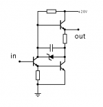
This type totem "just works", can use ordinary bjts, darlingtons and mosfets (with values adjustment); zeners, diode strings and leds... (the top is obviously a "modulated ccs"). Adjust voltages and values for your app of course.
A complimentary AB can have a huge advantage at HV because both output collectors/drains are "AC cold"; there is no stray capacitive bleed/leak to heatsinks.
A complimentary AB can have a huge advantage at HV because both output collectors/drains are "AC cold"; there is no stray capacitive bleed/leak to heatsinks.
Attachments
I think what you draw has to be class A.
One thing I might try is a single NPN on top and simple compound pair bottom. Whilst a nasty idea it should work. I agree about the virtues of class AB for this use.
All should read this link. 1956 amplifier of H C Lin. He patented the modern FET and the op amp.
Oral History Lin Page7 RCA GermaniumTransistors Audio
Yep the above totem is class-A. It's more economical than other variants because it voltage-clamps the bootstrap cap so it can be lower voltage type; smaller and cheaper. Will work regardless.
I think what will get built will be the worlds best example of a very bad power amp that will be 100% as good as it needs to be. Lawn mower motors are like that. Mostly excellent without being better than they need to be. If we were to ask a lawn mower engine to drive a generator I guess we would find it short lived.
I might fit a long tail pair input as it simplifies layout. I then give a DC reference to the +ve input and signal to the feedback side. I would like a NPN PNP output stage. I doubt it's the best way. Many NPN's are switch-mode devices so ideal.
I might fit a long tail pair input as it simplifies layout. I then give a DC reference to the +ve input and signal to the feedback side. I would like a NPN PNP output stage. I doubt it's the best way. Many NPN's are switch-mode devices so ideal.
- Home
- Amplifiers
- Solid State
- JLH 10 Watt class A amplifier