You are using too high a bias current so of course the amplifier it will get excessively hot. Why not read the original article (see tables 1-3) where a current of only 1.25A is specified for 10W/8R output? http://sound-au.com/tcaas/jlh1969.pdf....but i use a big heatsink per amplifier because it seems that they become otherwise very hot. ...
If you want more power, first you need a higher power supply voltage, up to the recommended limits but the simple design is limited to 15W, just like it says. Practically, you will scarcely notice any difference between 15 and 20W.
The TCAAS site is well worth a visit,very informative. The 2SC5200 is a 120V 12A device,but it is important to make sure the die temperature is kept as low as possible.Don't forget the insulating pad has a thermal resistance,which may raise the die temp. to unacceptable levels.I prefer to polish the area of the heatsink where the transistor is to be mounted to a mirror finish using wet & dry abrasive paper,soap filled wire wool scouring pads then finished off with "Duraglit" polishing wadding.Each output transistor is mounted on its own heatsink and insulated from the main metalwork.I am using a pair of 15W Monoblocks ,which sit behind the speakers.I fitted a cardboard "chimney" over the heatsinks,the increased air flow reduces the h/s temp.by a few degrees.If an output of more than 25 Watts is required,then Class AB should be considered,otherwise the heatsinks become unwieldy (not to mention expensive ! ).The 2SC5200 works well with its PNP compliment, the 2SA19??. With a class AB it is important to have a reasonable Iq ,300 -500 mA ensures that the first Watt is class A,and the possibility of cross over distortion is eliminated.It is well worth reading John Linsley-Hood's thoughtful article on "Listener fatigue" and "The Transistor sound" which plagued early solid state amps.These he put down to lack of loop gain during cross over.
It's very difficult to get the thermal resistance between the transistor and the heatsink down to levels close to what your heatsink is capable of. You'll see references to an infinite heat sink, meaning just taking into account the thermal resistance from junction to case, and from case to heatsink, which have to be added to your 0.5K/W.
I will use ceramic insulator plates from 0.6mm and Antec Formula 6 nano diamond thermal compound. I will test if i can get 4A or not...
Each psu can give max 9A so i have alot of headroom...
Per channel i will use a heatsink from Fisker, <0.28K/W and the measurements are 200x200x84 (SK418 from Fisker)
Each psu can give max 9A so i have alot of headroom...
Per channel i will use a heatsink from Fisker, <0.28K/W and the measurements are 200x200x84 (SK418 from Fisker)
In theory we should be root-two-ing that to 2.0A if we have a 4R load and c.3A for 10W/2R. if we want to "double down" (as is the fashion) it's 2.5A and 4.5A, (or thereabouts)a current of only 1.25A is specified for 10W/8R output?
Now speakers that presented loads like that weren't common when JLH did his design but they are unfortunately all too common now (which is why the NAD 3020 is still an iconic amp but that's another story). If your devices can deal with the heat you've then got the option of setting the bias to deal with the most difficult load your speakers present.
Last edited:
i bought some small boards with tip41C output transistors,(1969 design) i changed them for 2sc5200 (selected for almost the same hfe. the boards are giving 10w eacht, so i would set 2A idle current @24V. (single rail, i have big heatsinks (o,28K/W) weighting 3.5kg per piece.
I would like to have 20w, so 4A idle current, is that possible? (the output transistors are sufficient and the heatsinks are capable too...
You want 20W (rms):
4ohm---> 20w=VxI=(V^2)/R---->
20wx4ohm=80V^2----->(circa) 9V (rms)
So your minimum supply will be:
9x1.414x2=(circa) 26V
I=13/4=3.25A=(circa)2.23Arms
8ohm---> 20w=VxI=(V^2)/R---->
20wx8ohm=160V^2----->(circa) 12.65V (rms)
So your minimum supply will be:
12.65x1.414x2=(circa) 36V
I=18/8=2.25A=(circa)1.6Arms
In the end you want the best (worst) of both impedances.
Your final supply, for a 20W 4&8ohm capable single ended amplifier will be:
36V
3.25A
Better:
40V
3.5A
Your dissipation will be:
40x3.5/2=70W (per device)
20Wrms (real output power)
Efficiency: ((20Wx1. 414)/140W)x100=20.2%.
This is class A.
70w are easily manageable by the 2sc5200.
20V 3.5A are in the SOA.
But you must be sure your heatsinks are large enough.
iperv
Edit: note: 9x2.23=(circa)12.65x1.6=(circa)20Wrms.
Last edited:
I will see what's working 🙂
another question is, do i need a time-delay board for the loudspeakers because i do not want to have a popping sound when i power-on the amplifiers...
thank you
another question is, do i need a time-delay board for the loudspeakers because i do not want to have a popping sound when i power-on the amplifiers...
thank you
the single polarity supply version has to charge the AC coupling capacitors up to their final DC blocking voltages.
You must allow a route for the current to pass to allow that charging to occur.
You must allow a route for the current to pass to allow that charging to occur.
You can often minimise turn-on "thump" by slowing the rate of rise of the centre rail with a large capacitor on the input bias chain. The best bias method I've seen is to use a potential divider using relatively low value resistors (e.g. 10-22k) with a 100uF cap to ground, then taking a base feed resistor from the tap (e.g. 22k) to the input transistor base.
Maybe my hearing is not so good but I have been enjoying this amp more than my boutique 300B tube amp with fancy tubes. I am keen to hear other class a amps with a similar sound and a little more power.. Any suggestions?
Hi Frangus,
If you are willing to experiment a bit, there are variations on the JLH Class A amp that give power outputs of 15, 20, 25 and up to 40/50 watts - with the associated heat dissipation.
I suggest that a look at Ron Elliott's pages
Elliott Sound Products - The Audio Pages (Main Index)
and the Class A site that he hosts.
The Class-A Amplifier Site
It has a wealth of information that may be of interest and help.
Kind regards
Mike
Absolutely. At least read about this version, as modified by TCAAS pages author, Geoff Moss. The builder's comments will whet any music lover's appetite, whatever you make of the actual design and requirements. For normal speakers, I believe you'll be able to use less bias current and heatsinking than is recommended there for use with ESLs. That should make it even more attractive.I suggest that a look at Ron(sic) Elliott's pages....It has a wealth of information that may be of interest and help...Mike
Thanks for the info. I wish there boards available for these newer designs. I am not as tech savvy as you guys
Thanks for the info. I wish there boards available for these newer designs. I am not as tech savvy as you guys
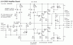
I bought a pair of bare pcbs from an Ebay seller a few years ago.
They were the high power design with two pairs of output transistors. Probably a copy from the schematic above.
Be worth a look?
I got a PM asking for these and found I couldn't add attachments to my reply. So here are the files. The Gerbers are in the Fabrication-Files folder. Be sure to read the readme file there and the other readme file in the main folder.I have information from Geoff including PCB fab files and a suggested bias adjustment procedure for any that are interested. I built this version and have enjoyed it immensely.
Attachments
jlh 2005
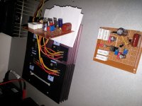
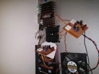
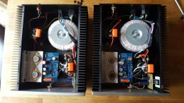
I finished both channels of my JLH 2005 and tests went well, even tried one channel with 2sc5200 (one pair only) and sound is not good as with isc 2sc2922 (2 pairs). I guess that's because they are cheap copies from ebay 🙂. Now I need to find some nice heatsinks and make some housing for this jewel.
Some pics:
(I hope I can do test in stereo tonight)
Attachments

Nice setup, JLH 1969 has sweet sound indeed. I'm waiting mj15003g from Farnell to replace 3055's - can't wait to hear the difference.
(Are those 3055's originals or China fakes?)
(Are those 3055's originals or China fakes?)
Just finished my JLH1969 with Mosfet capacitance multiplier. Chassis and PCB from China and all other components from my old stock and also from Farmell, UK. Indeed very sweet sound.
Gentlemen,
Before the dual supply version was around, I remember Mr. Hood himself
commenting on bridging the 69 version, both increasing the power output
and eliminating the output capacitors.Using MJ15003's, pushing the supply
voltage somewhat above 30 V and the bias current to 2.5 A, it seems possible
to get around 50 W on 8 R speakers. Of course you always have the option
of utilizing multiple output devices and pushing the voltage and current a little
higher, but somewhere on the way to higher power, heat gets in the way.
I believe power output is not as significant a property of amplifiers as it is
often quoted. A 10 W 69 version will suit your needs most of the time. When
it doesn't, there are other fine amps.
Best Regards
Selim
- Home
- Amplifiers
- Solid State
- JLH 10 Watt class A amplifier